Over the last several years we have seen a steady evolution in how diaphragms are considered in analysis programs.
Evolution of Lateral Load Analysis
Prior to the mid-1980s, before structural analysis software was readily available to engineers, most engineers analyzed buildings for lateral loads using simplified manual methods, considering the frames as individual 2D frames. Loads were considered as nodal loads, which had to be calculated by hand (the codes were much simpler back then) and the engineer had to decided how to distribute the loads to each frame. This was generally based either on tributary areas or on relative stiffnesses of the frames. It is interesting to note that implicit in the former approach was the assumption of a flexible diaphragm and implicit in the methodologies commonly used in the latter approach was the assumption of a rigid diaphragm.
With the advent of personal computers, rudimentary analysis programs became generally available, but those programs merely mimicked what engineers were previously doing manually: engineers analyzed most buildings for lateral loads by simply modeling separately each individual 2D frame and applying the nodal loads that the engineer manual calculated. There were no capabilities to analyze the 3D frames nor to automatically generate wind or seismic loads in those programs.
By the late 1990s, however, the technology evolved. Three-dimensional models could now be created and analyzed within a software program, and lateral loads could now be automatically generated and distributed to the lateral frames in the model. Nodal loads could still be manually calculated and meticulously applied if desired, but the software could also automate the process of applying the wind and seismic story forces and distributing those loads to the various frames. Because of severe limitations on computer memory and speed, simplifying assumptions and methodologies were necessary. The assumption that the diaphragm is infinitely rigid was widely implemented because it dramatically reduced the size of the analytical model while providing a mechanism for distributing the wind and seismic loads to the frames. At the time it was impractical or impossible to actually model the diaphragm properties and include the diaphragm as part of the analytical model.
Diaphragm Modeling Today
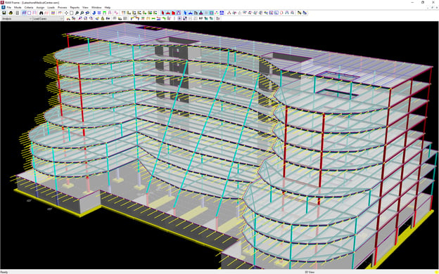
Today’s computers are exponentially faster and have much more capacity for larger and more complicated analytical models. This includes the ability to explicitly model the diaphragms and include them in the analysis. But it is still common today for engineers to consider diaphragms to be either flexible (i.e., no significant stiffness) or to be rigid, and to analyze them that way without any modeling of the diaphragms.
Why is it important to know this history? First, it is important to understand how and why commonly accepted practices and method originated. It helps justify using a particular approach, or demands that something different be done. While engineers now rely heavily on automated technology, it is sometimes necessary to do hand calculations to verify results; knowledge of this history can help with that manual process.
Second, it helps answer confusion about the methods used and the results obtained, and clarifies best practices and methods for particular conditions. This understanding aids in determining the ramifications of employing any particular diaphragm modeling methodology, and guides the engineer in mitigating the shortcomings inherent with each.
This article is the first in a series on diaphragms that will focus on some differences in the types of diaphragm models that can be used, as well as the corresponding results from using each type. We will also cover various tips and critical factors to keep in mind when using each type of diaphragm model.
The next article in this series is "Types of Diaphragms."