The pump affinity laws are a way to compare pump performance when parameters like speed and impeller diameter change. For a given pump impeller and casing, the pump affinity laws can relate pump performance to pump speed according to
Qa = Qf (na/nf)
Ha = hf (na/nf)2
Pa = Pf(na/nf)3
Where Q = flow, h = pump head, P = pump power, n = speed, f = value at full speed, a = value at some actual speed na
Possible Energy Savings
Therefore, in theory, an operator can reduce the pump relative speed from full speed to 80% of full speed and save (80%)3 = 51% of the energy. Anyone believing this would be crazy not to turn the pump speed way down and save all sorts of energy. How is this logic flawed?
The current technology for converting a constant speed pump into a variable speed pump is a variable frequency drive (VFD). In certain situations, converting a pump into a variable speed pump can save a considerable amount of energy. However, in some cases, installing a VFD won’t even pay for the cost of the VFD, and in others, it’s possible to use even more energy by using variable speed pumping. How can that be?
Problems in Achieving Savings
First, the VFD itself uses energy to convert the input power frequency into lower frequency. This is sometimes referred to as the “parasitic” energy use of the VFD since it does no good. At full speed, this energy use is merely 2 or 3 percent of the input power, but as the speed slows down, the loss of efficiency increases.
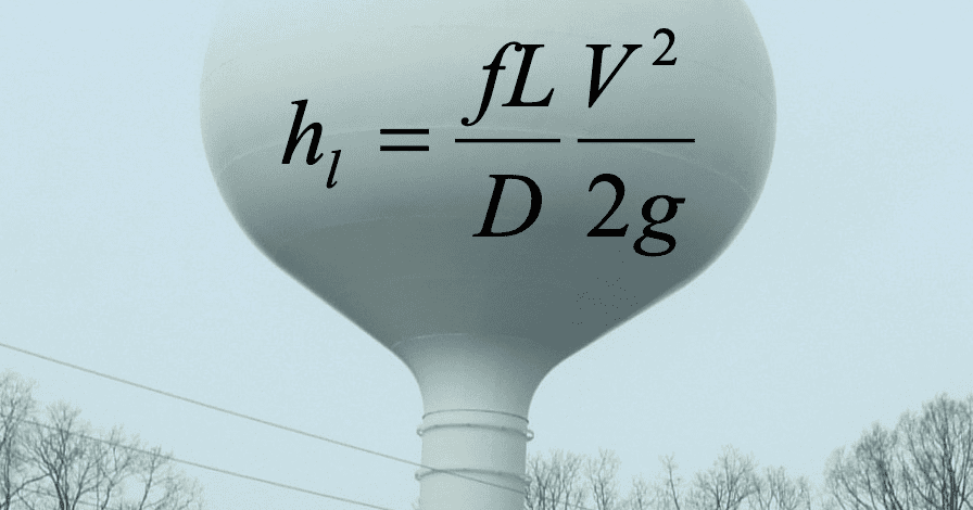
Second, and more importantly, the amount of energy savings depends on the system, as represented by the system head curve. The system head curve can be represented by
hs = hL + hf = hL + k Qb
Where hs = system head required to move the water, hL = lift, hf = head loss due to friction and minor losses, k = parameters to account for piping configuration, sizes, length, and roughness, Q = flow, b = head loss exponent usually ranging between 1.85 and 2.
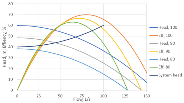
A typical water or wastewater set of pump head, pump efficiency, and system head curves, is shown below for pump speeds of 80, 90 and 100% of full speed. The pump operates at the intersection of the pump head and system head curves. At 100% of full speed, the pump will produce 70 L/s at a head of 50 m and an efficiency of 70%.
At 90% of full speed, the pump will produce 48 L/s, at a head of 45 m and an efficiency of 58%, not all that good. However, when the speed is turned down to 80%, in this case, the flow will be zero because the system head curve is above the pump head curve. The pump will not work at 80% speed even though it will continue to draw power. Blind application of the affinity laws would say that it should be running happily at 51% of full speed power.
Is variable speed pumping all that bad?
Variable speed pumping doesn’t always look this dismal. The best application for a VFD are cases where the system head curve can be fit to the equation (i.e. systems with no lift and relatively rough pipe).
hs = k Q2
Most water and wastewater pumping does not fit the above equation as much of the energy usually goes to lifting water to elevated tanks or lifting wastewater over a hill.
Nevertheless, I just read an article (apparently by a VFD sales engineer) that claimed that power consumption can be driven to virtually zero by using VFDs.
Is variable speed pumping bad? No, variable speed pumping can create significant energy savings when applied to the right situations. But the engineer specifying the pump configuration should analyze constant and variable speed pumping side by side and determine if an investment in VFDs is worthwhile. In the past, such calculations may have been tedious. But for the last decade, WaterGEMS and WaterCAD have energy costing tools which can perform such analysis with a few mouse clicks once the model has been built.
Plus, there are other considerations that come into play. The above analysis used a single system head curve, but there is really a band of system head curves depending on tank water levels, actual demands and performance of other pumps in the system. When these bands are very wide, variable speed pumping can be more attractive. (One example would be a manifold wastewater force main with a number of pump stations in flat terrain with widely varying flows due to infiltration and inflow.) These considerations can also be taken into account with WaterGEMS and WaterCAD.
More Information
There are a number of documents in the OpenFlows wiki and communities on modeling variable speed pumps, such as
I’ve also been doing some research on general guidelines on selecting variable vs. constant speed pumping. When I can generalize some results, I’ll share them on the blog.