Net Zero Goals
The COP26 global summit in late 2021 made important progress in a number of areas. Countries worked toward the aim of closing the gap, limiting global warming to 1.5 deg C. Bold collective commitments were made to:
- Curb methane emissions
- Halt and reverse forest loss
- Align the finance sector with net zero emissions (carbon-neutral) by 2050
- Ditch the internal combustion engine
- Accelerate the phase-out of coal
- End international financing for fossil fuels
Many countries pledged to achieve net zero by the middle of the century. To achieve this goal, plans have been made to adjust the energy mix with a strong focus on clean energy. Renewable sources such as solar, wind, and hydrogen play an important role in reaching net zero.
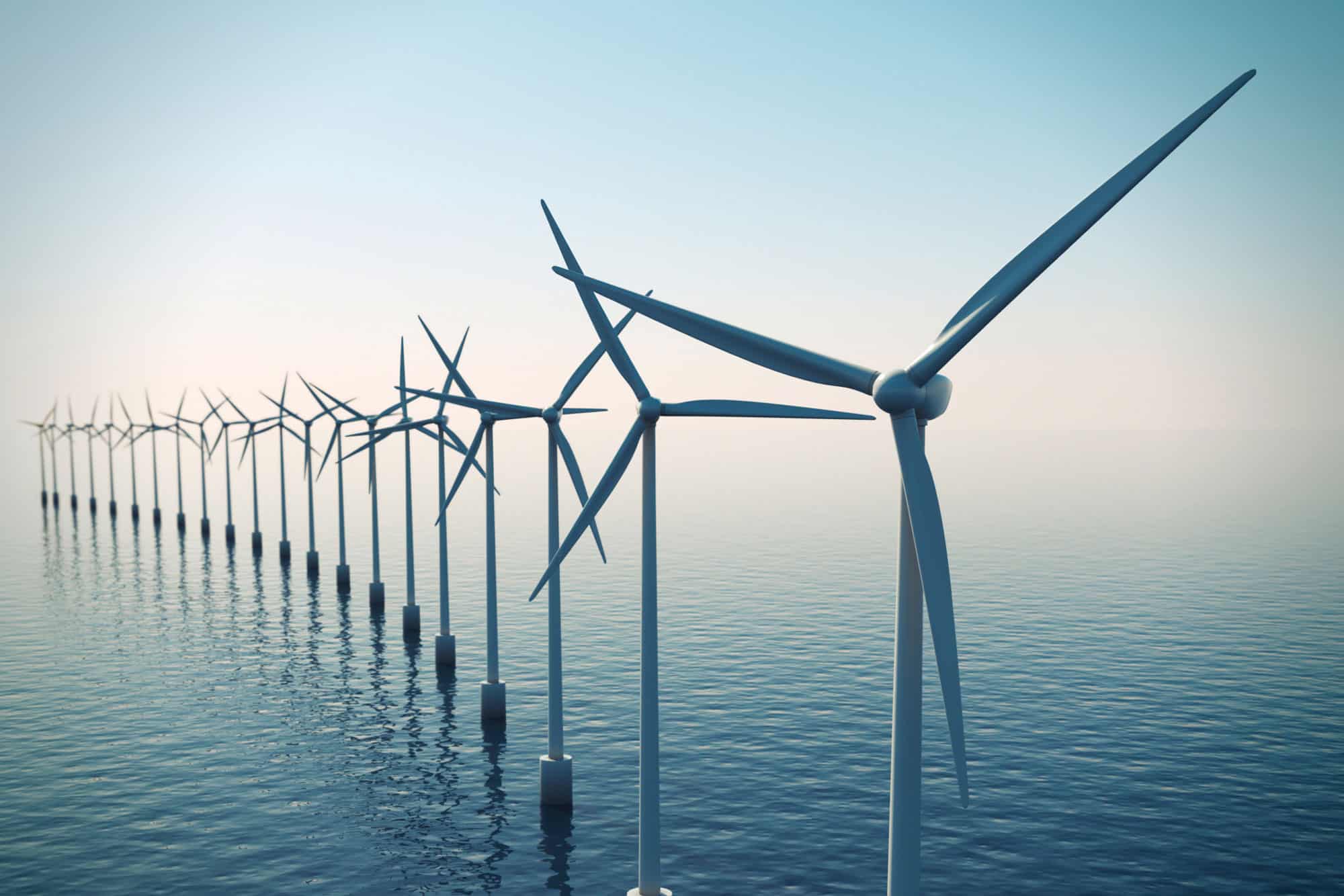
The Growth of Offshore Wind
In regards to wind energy, the onshore wind industry has grown for decades and has been adapted by many countries around the world. The offshore wind industry is relatively newer; however, it has witnessed rapid expansion in the United States, Europe, and Asia in recent years. Furthermore, the cost of offshore wind has fallen dramatically, and it is speculated that this will become the cheapest form of energy in the industrialized world.
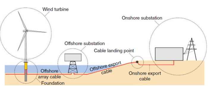
Figure 1: Typical layout of an offshore wind infrastructure connecting to the onshore transmission grid.
Figure 2 from the GWEC 2021 report shows the constant compound annual growth rate of 11% from the wind energy since 2015. The new installation of offshore wind has increased year-on-year, with 35GW additional capacity seen in 2020.
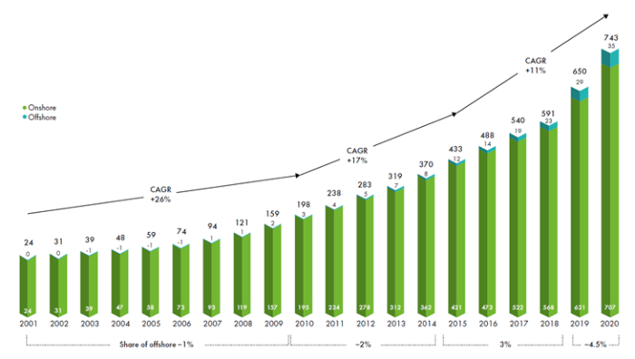
Figure 2: Global CAGR of wind energy (GWEC 2021).
The US Department of Energy, in its recent market report, showed an overview of the already announced offshore wind projects around the world mounting up to 29GW of new capacity in 2026. China reached its highest annual addition in 2021, while the United States, United Kingdom, Poland, and the rest of Asia expect exponential growth of new installations in the next five years.
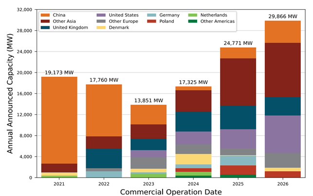
Figure 3: Offshore Wind Developer-announced COD.
The huge demand in capacity has also led to growing individual turbine capacity and larger rotor blades. It is expected that by 2035, the turbine capacity could reach 17MW, at the height of 495ft above sea level and rotor blades sweeping an area with 820ft in diameter.
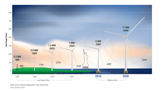
Figure 4: Sizes of wind turbine structures.
Types of Offshore Wind Turbine Foundations
Foundation selection for these offshore structures plays an important role in the overall concept design for offshore wind farms. There are significant financial implications attached to the choices that are made. Typically, foundations account for 16 to 34% of the overall costs, depending on the location and size of the wind farm.
Due to the vast size of a wind farm, there will be varying seabed conditions, including water depth and distance from the shore. As a result, the loads on the foundations will change, and ideally, the best design will be to design each foundation individually, which will give rise to a customized foundation design for each turbine location. However, from an economic point of view, it is desirable to use just a few foundation types to reduce costs and improve efficiency because the process of fabrication and installation can be carried out using the same installation vessel. Most North European developers prefer one type of foundation (either monopiles or jackets) in a site. This consideration often dictates the layout of the farm to avoid deeper water or soft, locally available mud.
In addition, many other aspects must be considered while choosing and designing the foundation for a particular site. They include:
- Ease to install under most weather conditions
- Varying seabed conditions
- Aspects of installation including vessels and equipment required
- Local environmental regulations (noise)
A general guide to foundation types in terms of water depth could be described as follows:
- Typically, for near-shore areas where WD is less than 30m, a monopile foundation would be the suitable and economical choice
- Going further and deeper up to 60m WD, jacket structures on suction buckets or pile foundations would be appropriate
- Deeper than 60m is the playing field of regular offshore floating systems, such as tension leg platform, spar, or semi-submersible
Each of the foundation types poses different sets of technical challenges.
Fixed foundations need to address concerns of:
- Pile design to withstand environment and dynamic loads from turbine
- Multiple seabed design conditions covering the wind farm, loadout, and installation
Floating foundations should be designed for:
- Safe operation under extreme pitch, roll, and heave wave motions
- Stability design and dynamic coupling of translational and rotational platform motions and turbine motions
- Dynamic behavior of mooring lines
- Buoyancy to support full weight of turbine, tower, and platform
- Anchoring system, mooring, ballast, and buoyancy factors dependent on spar, TLP, or semi-sub
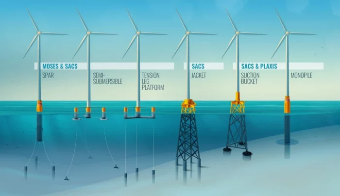
Figure 5: Types of wind turbine foundations, and Bentley software to address each type of foundation.
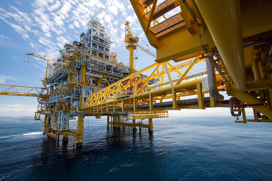
Foundation Design for Offshore Wind Turbines
The design of offshore wind structures found its origin in following the design of offshore oil and gas structures. The aim of the foundation is to transfer the loads of the substructure and superstructure safely to the ground. The loads on the foundation depend on the foundation system.
While the experience gained from offshore oil and gas operations can be applied, it is important to highlight the significant differences between these two types of structures. These differences deserve special attention. It is now widely acknowledged that offshore wind turbine structures are unique in their features. The most important difference with respect to oil and gas installations is found in large-scale offshore wind turbine structures where a heavy rotating mass is placed at the top of the slender tower. Offshore wind turbine structures are dynamically sensitive, because the natural frequencies of these slender structures are very close to the excitation frequencies imposed by the environmental and mechanical loads.
For typical 3.6MW turbines, the first natural frequency (eigen frequency) of the whole system is close to 0.3 Hz and for the corresponding 8MW turbine is 0.22 Hz. The frequency of the rotor of the wind turbine is in the range of 0.2 Hz. Typical wind turbine blades weigh 30t, and as a result, 90t is rotating at the top of the tower. On the other hand, the natural frequencies of offshore oil and gas platforms are more than 0.6 Hz and the most important cyclic/dynamic loading is the wave having frequencies 0.1 Hz (typical North Sea value). The forcing frequencies are not very close to the natural frequencies, making oil and gas platforms less sensitive to dynamics. (Bhattacharya, 2019, Design of Foundations for Offshore Wind Turbines.)
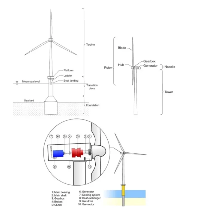
Figure 6: Typical components of an offshore wind structure with monopile foundation.
Figure 6 shows a typical monopile-supported wind turbine and a pile-supported fixed offshore jacket structure. It is very clear that the ratio of horizontal load to vertical load is very high in offshore wind turbines when compared with fixed-jacket structures. As a result, the monopile is a moment-resisting foundation.
Let’s compare the single large-diameter monopile and multiple piles supporting a jacket in the load transfer mechanism. In the case of monopile-supported wind turbine structures, the load transfer is mainly through overturning moments, where the monopile/foundation transfers loads to the surrounding soil, and therefore there is lateral foundation−soil interaction. On the other hand, for a multiple support structure, the load transfer is mainly through push-pull action − i.e., axial load, as illustrated in Figure 7.
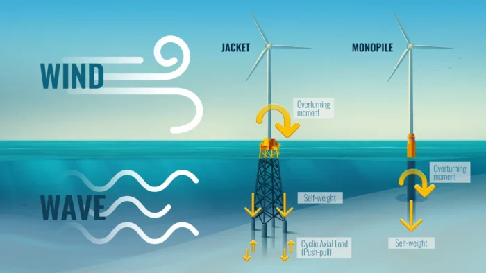
Figure 7: Load transfer mechanism for monopile and jacket on piles.
Next let’s look at a particular type of floating system known as spar-supported floating offshore wind turbines with catenary mooring and suction caisson anchors. This is effectively the example of the Hywind concept, the first floating offshore wind farm. For foundation design, it is necessary to estimate an upper bound for the ultimate load on the anchor.
This can be obtained by taking the configuration where the mooring line is completely stretched and there is no part of it lying on the seabed. This is very similar to the configuration of a single taut mooring line. In this case, the load is transferred directly to the anchor without the effect of soil friction on a horizontal section of the mooring line.
Furthermore, in this configuration, the angle of the mooring line at the seabed is also maximal, which impacts the inverse catenary shape at the anchor. This scenario is unlikely to happen to a floating oil and gas platform on mooring.
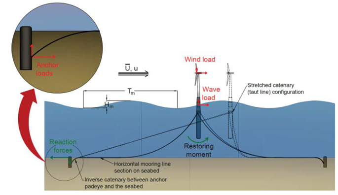
Figure 8: Load transfer for floating wind turbine systems (Bhattacharya).
Offshore wind foundation design also has to deal with the most complicated set of loadings on an offshore structure. DNVGL-ST-0437 (Loads and Site Condition for Wind Turbines) requires the structure to be designed for ultimate and fatigue strength of structural members and time history analysis shall be used for dynamic problems of a non-linear nature.
Following are the loadings to be considered for offshore wind turbine design:
- Operational loads as the result from the operation and control of the wind turbine
- Inertia and gravitational loads (static and dynamic loads) acting on the wind turbine, resulting from vibration, rotation, gravity, and seismic activity
- Aerodynamic loads caused by the airflow and its interaction with the stationary and moving parts of wind turbines
- Hydrodynamic loads caused by the water flow and its interaction with the foundation structures (including wave loads, breaking wave loads, and sea current loads)
- Hydrostatic loads which may be applicable for hull-type structures, such as semi-sub
- Sea ice loads
- Seismic loads
- Boat impact loads
The load time series for the offshore wind turbine combining all the above external conditions are required. This means thousands of load cases are to be checked.
A typical Fatigue Limit State (FLS) design would involve 5,000 to 10,000 dynamic force time history analysis simulations, while typical Ultimate Limit State (ULS) design involves 10,000 to 15,000 dynamic force time analysis simulations. Each time history simulation can be 600 seconds long after the initialization of transient with analysis increment of 0.05 to 0.01 seconds. So typically there are 12,000 to 60,000 load cases to be solved for each simulation. This leads to a huge challenge of data generation of input files and directory structure for thousands of dynamic time history load cases. This process is both time-consuming and error-prone.
Bentley’s OpenWindPower software offers a complete engineering tool for designing both fixed foundations and floating platforms for offshore wind turbines. Read more about OpenWindPower, the industry-leading engineering tool for offshore structure analysis.