In my previous post I discussed conditions that require consideration of diaphragms as semirigid. In this article I will discuss what is involved in modeling semirigid diaphragms as well as some characteristics that semirigid diaphragms may exhibit, of which you should be aware.
Defining Analytical Properties of Slabs and Decks
Creation, analysis, and review of a model with Semirigid diaphragms requires considerably more effort by the engineer and more computing resources in the computer. If done properly it also gives the most realistic and correct design results. The first step is to define the analytical properties of the slab or deck:
For a concrete slab it is common to use the slab thickness and the concrete properties (e.g., Ec) to define the diaphragm stiffness; it may be appropriate to apply a cracked factor to Ec.
For concrete fill on metal deck it is common to ignore the contribution of the metal deck, and only use the concrete properties to define the diaphragm stiffness. Although some engineers consider the diaphragm to be only the depth of the concrete above the ribs, it would be appropriate to consider all of the concrete, including that in the ribs, since the concrete in the ribs contributes to the shear stiffness of the diaphragm in both directions; for most open-profile/trapezoidal decks this is most easily done by specifying a diaphragm thickness equal to the depth of fill plus one-half of the rib depth. For reentrant profile decks an equivalent depth can be calculated and used. Although unusual, some engineers apply a cracked factor to these diaphragms as well (in defense of the practice of ignoring a cracked factor for these decks I would suggest that the metal deck, acting compositely with the concrete, adds considerable stiffness, which we are ignoring, to make up for ignoring the cracked factor).
The stiffness of other types of decks is more difficult to define. For example, the stiffness of metal roof deck is dependent on the gauge of the deck, the attachment of the deck to the beams and to adjacent deck sheets, the beam spacing, and the susceptibility of the corrugated ribs to warping, among others. The Steel Deck Institute manual provides some guidance. Some engineers insist that different stiffness values should be used parallel to the span versus perpendicular to the span of the ribs. However, Section 3.1 of the Steel Deck Institute’s Diaphragm Design Manual 3rd Ed. shows the calculation of the stiffness, G’, without regard to the direction of the deck span, noting that “the average shear … is equal either along the panel direction or across the panels.” So, keep it simple.
The stiffness of plywood diaphragms is similarly difficult to define.
As I will discuss in a later article, it is generally not necessary to define these properties exactly.
Defining Extents of the Diaphragm
The next step is to define the extents of the diaphragm. This is generally the extents of the slab edge around the perimeter of the structure. All significant openings in the slab must also be modeled; if relatively large, these can significantly reduce the stiffness of the diaphragm. The connectivity of the frame columns, beams, and walls to the diaphragm must then be specified; these members must share a common node with the diaphragm. In the RAM Structural System this is done automatically; all frame members within the slab edge boundaries are automatically connected to the diaphragm.
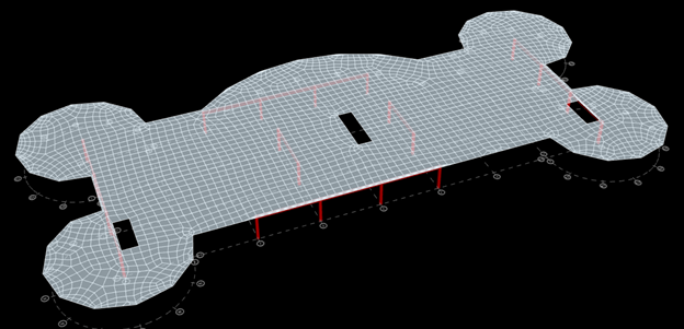
With the diaphragm stiffness properties defined and the diaphragm boundaries identified, the next step is to mesh the diaphragm into discrete plate or shell elements. Some programs, such as the RAM Structural System, automatically create the diaphragm mesh as seen here:
With the addition of all of these mesh elements the analysis will take considerably longer than for the model with rigid diaphragms. Furthermore, the coarseness of the mesh (the size of the plate elements) is a consideration in both the accuracy of the results and the time required for the analysis, with a generally small impact on the former and a large impact on the latter. This will be discussed more in the next article.
Defining Loads on a Diaphragm
The final step is to define the loads on the diaphragm. Diaphragm loads is too broad a topic to cover in this article, I will discuss it in the future.
Because the semirigid diaphragm is less stiff than a rigid diaphragm, the analysis is likely to indicate a longer fundamental building period for the model with the semirigid diaphragm than the rigid diaphragm; the longer period may result in a smaller base shear for seismic loads. This is appropriate. The rigid diaphragm analysis may give shorter building periods and, hence, larger base shears, which are conservative. In most cases, however, the difference is expected to be minor.
Diaphragm displacements and story drifts given by the semirigid diaphragm analysis will differ somewhat from a rigid diaphragm analysis due to the locally greater (or smaller) deflections that result from not being constrained by the rigid diaphragm assumption. In regions of the diaphragm not immediately adjacent to the lateral frame members, these differences may be particularly greater; the validity of those values reported by the semirigid analysis should be questioned because although the properties of the slab or deck are more accurately defined, the diaphragm displacements at locations away from the lateral frames may be exaggerated without consideration of the constraining effects of the gravity framing, which normally isn’t included in the lateral analysis for simplicity.
It is difficult to perform independent verification calculations other than some simplified approximations. Furthermore, the output is more complicated and voluminous. For example, instead of merely reporting the displacement and rotation of the diaphragm, the output includes the displacements of all of the mesh nodes. This can be less burdensome if the software has the appropriate visualization and reporting tools. For example, RAM Structural System has a command that reports the deflection, drift, and drift ratio for any explicit location on the diaphragm selected by the user; the user needs to merely select the location, rather than digging through line after line of mesh node deflection values.
There is often some apprehension over the possibility of improperly meshing the diaphragm or assigning incorrect stiffness properties. In the next couple of articles I will present the results of an informal study on the impacts of varying mesh sizes and inaccurate properties on the frame forces and displacements.
The next article in this series is Impact of Mesh Size in Semirigid Diaphragm Analysis.