For a large structure, the architectural display is one of the most vital aspects of a building’s design, and of nearly equal importance is the building facade.
Structures can boast huge front facades that support glass panels to retain the aesthetic beauty with minimalistic appearance. These types of buildings may include:
- Shopping malls
- Commercial complexes
- Airport terminals
- Museums
The architect wants a minimum of supporting structures while the engineer wants to optimize the supporting structures.
To support the huge weight of glass panels and the lateral action due to the wind load, architects use a conventional method: steel framing systems (Figure 1a), however, they tend to be bulkier as well as clumsy.
Another technique is to leverage tensile capacity of the “Tension Only” members, like cable elements.
Since, in general, members have better load bearing capacity when in tension than in compression (because the compressive buckling effect is absent here), and we can somehow utilize the members to bear the loads by virtue of their tensile properties, then we could reduce a significant amount of material. That’s why cable-stayed bridges are so popular.
The tensioned cable glass façade system (Figure 1b) utilizes the tension bearing capacity of the cable to bear the gravity as well as the lateral loads the façade experiences. These cables are pretensioned ̶ just like the strings of a tennis racquet ̶ to bear the loads.
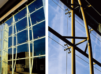
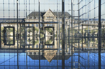
Figure 1a: Conventional method: steel framing. Figure 1b: Tensioned cable glass façade system.
As a result, these systems are architecturally pleasing. The structural support for the glass façade uses spider fittings to connect the pieces of glass (Figure 2). The cables that join the concrete slabs in vertical directions are connected by the prestressed stainless-steel rods/cables. Specially made steel trusses or struts are connected in- between and the spider fittings are secured with those trusses. Glass is connected in the spiders using rotules, and weather sealant is applied between the glass joints. Combined, it gives a very lightweight look to the glass façade.
.png?width=369&name=Figure%202%20(1).png)
.png?width=335&name=Figure%202%20(2).png)
Figure 2: Spiders
Five Benefits of Pretensioned Cable Façade Systems:
- Significant options for aesthetic purposes.
- Less bulky than traditional truss systems.
- Reduced obstruction of incoming light.
- The cables in tension behave like springs, with vibrations developing along the length of the wall, helping absorb winds of varying speeds along different areas.
- Fast and quality installation.
Structurally, these cable members are geometrically non-linear in nature because of their high elasticity and flexibility where the large deflections are very common. And, to capture this nonlinear response, solving the nonlinear cable problem is essential.
Using STAAD advanced 3D structural analysis and design software, both the linear and nonlinear cable analysis options are available.
Linear cable analysis is conducted by using the MEMBER TENSION command in conjunction with the MEMBER CABLE command. This method works satisfactorily, as long as the cables do not go into compression, but is not suitable for small deflection.
Nonlinear cable analysis, on the other hand, is the most robust analysis procedure for cable members. In addition to their ability to handle a nonlinear cable problem, this method also considers the catenary cable theory (Figure 3b), and so this method is suitable for large complex models having many interconnected cables.
This nonlinear cable analysis approach is even more rigorous when the stiffness matrix is modified at every iteration. This is also known as the TANGENT STIFFNESS MATRIX method (Figure 3a).
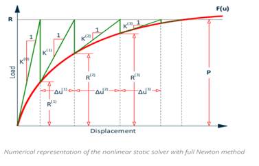
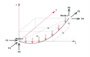
Fig.3a: Tangent stiffness Fig.3b: Catenary cable element
Modeling in STAAD
STAAD can handle these kinds of non-linear cable problems very effectively. For example, take the simple cable net structure in Illustration (Figure 4). These pretensioned cables are running through the node assembly through its perforation. These nodes are connected to the spider which holds the faced glass assembly through the rotules.
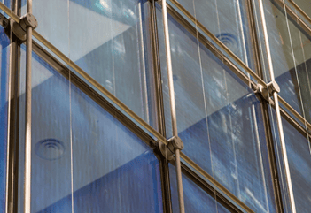
Figure 4: Pretensioned cable mesh.
We modeled similar projects for a client in STAAD (Figure 5). The cable mesh looks a bit similar.
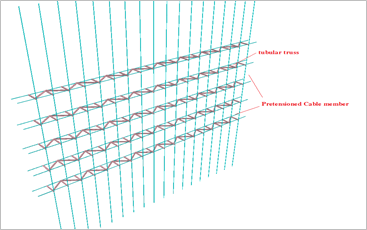
Figure 5: Pretensioned cable system.
.png?width=330&name=Figure%206%20(1).png)
.png?width=410&name=Figure%206%20(2).png)
Figure 6: Loading acting on pretensioned cable system (STAAD model).
If you use a normal linear analysis, the program couldn’t effectively consider the nonlinear behavior of the cable, and so you would produce a high unrealistic displacement leading to an instability situation.
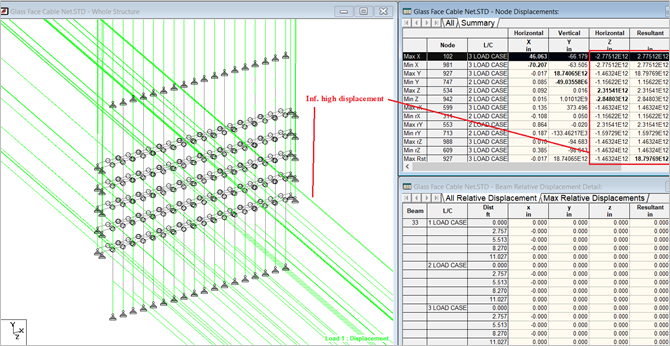
Figure 7: Linear cable analysis (unstable with high displacement).
We then started using the nonlinear cable analysis with initial tension value of 2.4 KN.
After analysis, the solution couldn't be converged. You can see that the solution is diverging (Figure 8) for the gravity load case. The result is infinitely high displacement against the gravity load.
.png?width=359&name=Figure%208%20(1).png)
.png?width=384&name=Figure%208%20(2).png)
Figure 8: Nonlinear cable analysis (2.4 KN initial cable tension).
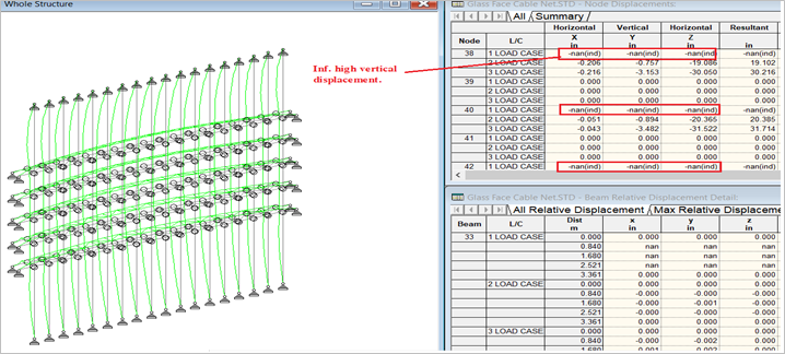
Figure 9: Nonlinear cable analysis (2.4 KN initial cable tension). Infinitely high displacement.
Next we started increasing the initial tension value from 2.4 KN to 24 KN.
This time the solution is converged and so the displacement results are within the realistic limits, even though they are high at a few nodes. Upon further increasing the initial tension, these displacement values could be brought to the allowable range.
-1.png?width=388&name=Figure%2010%20(1)-1.png)
.png?width=295&name=Figure%2010%20(2).png)
Figure 10: Nonlinear cable analysis (24 KN initial cable tension).
When running the model with nonlinear cable analysis, the program effectively stabilizes the solution by providing the actual displacement the facade experiences. At the desired solution, the glass panel would be hanging firmly to the cable mesh.
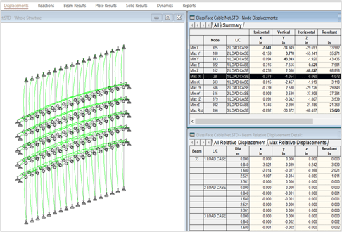
Figure 11: Nonlinear cable analysis (24 KN initial cable tension). Stable displacement.
Figure 12 is another example of a pretensioned cable façade system.
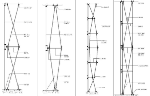
Figure 12: Pretensioned cable facade system.
.png?width=330&name=Figure%2013%20(1).png)
.png?width=270&name=Figure%2013%20(2).png)
Figure 13: Pretensioned cable façade system.
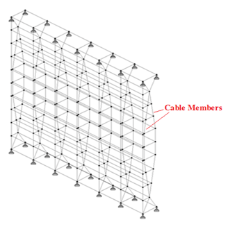
Figure 14: Pretensioned cable façade system (STAAD model).
.png?width=390&name=Figure%2015%20(1).png)
.png?width=610&name=Figure%2015%20(2).png)
Figure 15: Linear cable analysis (extremely high displacement).
.png?width=320&name=Figure%2016%20(1).png)
.png?width=494&name=Figure%2016%20(2).png)
Figure 16: Nonlinear advanced cable analysis.
.png?width=480&name=Figure%2017%20(1).png)
.png?width=622&name=Figure%2017%20(2).png)
Figure 17: Nonlinear advanced cable analysis (stable displacement).
