STAAD.Pro is generally associated with the analysis and design of steel structures. However, add-on components that are available with the program make it an efficient and powerful tool for concrete design also. Tools such as STAAD Foundation Advanced, and RCDC - FE give engineers the means needed to design and detail concrete structures.
In many design offices, slabs and foundations are either:
- Included as part of the superstructure model and thus analyzed along with the beams and columns, or
- Modeled as an independent local structure for analysis and design using the Finite Element Method (FEM)
In this article, we focus on the capabilities of various tools for handling these “planar” elements, namely, floor slabs and foundations, using STAAD.Pro, RCDC - FE, and STAAD Foundation Advanced.
This article focuses on the following topics:
- Typical workflow for slabs and foundations
- Analysis considerations for concrete slabs and foundations
- Discussion on main design requirements
- Discussion on rebar detailing
- Generation of reports and drawings
Choice of Software for Slabs and Foundations
Two of the options available to STAAD.Pro users looking to design floor slabs and mat foundations are:
| Structural Element | STAAD Foundation Advanced | RCDC - FE |
| Floor Slabs | Cannot Handle |
See "Workflow for Design and Detailing Floor Slabs in RCDC - FE"
|
| Mat Foundations | See “Workflow for Mat Foundations in STAAD Foundation Advanced” | See “Workflow for Mat Foundations in RCDC - FE” |
Typical Workflow - Slabs or Foundations
Any structural project undergoes typical stages such as:
- Model generation and preliminary assessment
- Refinement of the model and final analysis
- Concrete design (determination of reinforcement required)
- Rebar detailing
- Generation of drawings
- Generation of calculation of reports and bill of quantities
At each stage, various software is required to be used. Similarly, for parts of the structure, there are various stages of workflow. The most typical workflow for floor slabs and mat foundations would be as follows.
Workflow for Modeling and Analysis in STAAD.Pro
- Create model in plan (usually X-Z plane) to match the geometry
- Create the structural elements like beams, columns, shear walls, and floor slabs
- Apply appropriate loads on the slab and other elements as required
- Analyze the structure with appropriate support conditions, either (a) idealized as pinned, fixed, and springs, or, (b) if desired, the mat foundation can be included with the superstructure model.
- Review the analysis results for deflection, stability, etc.
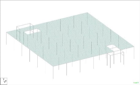 Typical slab model in STAAD
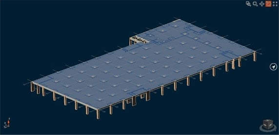
Typical foundation model in STAAD
Workflow for Design and Detailing Floor Slabs in RCDC - FE
- Import the STAAD superstructure model in RCDC - FE for slabs.
- Set appropriate design parameters and settings
- Finalize the design and detailing for various parts of the slab
- Generate detailed drawings and other reports like calculations, etc.
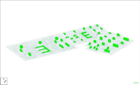
 Flat slab model after importing from STAAD
Workflow for Mat Foundations in STAAD Foundation Advanced
- Import the reactions from the superstructure model if that is one of the sources of the loads on the mat
- Generate a physical model of the mat foundation in STAAD Foundation Advanced and assign the soil/pile support parameters, as well as loads directly acting on the mat (if any)
- Create an FE mesh of the mat and perform the analysis of the mat FE model
- Generate the required calculation reports
- Create the preliminary design for flexure and punching with certain settings
Note: For detailed design and detailing, the STAAD model created through STAAD Foundation Advanced can be used and imported in STAAD Advanced Concrete.
Workflow for Mat Foundations in RCDC - FE
Prerequisite: The mat foundation must be analyzed as part of the superstructure model in STAAD.Pro or there could be an independent STAAD model for the same. This model can also be extracted from STAAD Foundation Advanced.
- Import appropriate STAAD model in RCDC - FE
- Set appropriate design parameters and settings
- Finalize the design and detailing for various parts of the mat foundation
- Generate detailed drawings and other reports like calculations, etc.
Floor Slabs - Technical Discussions
The slabs of the building are very important elements of the structure which support the major parts of the load that act on the structure. Often “flat slabs” are used for this purpose. These slabs are supported directly on columns. Generally, beams may be present in a few locations. These need to be analyzed and designed with special care.
Some of the important points to be noted for the model are:
- The slab thickness (and drop panels if they exist) must be proportioned as per provisions of the design code
- The mesh size adopted should be fine enough to have reasonable parts of the span, but should not be too fine
- The deflection check should be performed as per cracked sections
- For line load, like walls, appropriate “dummy” beams should be modeled for better load distribution
- The beams where present should be proportioned for the load they support
Mat Foundations - Technical Discussions
Mats are typically supported on soil or piles or a combination of the two. Soils like clay and sand are a flexible medium, so the preferred method is to represent it as a number of discrete translational springs at every node of the finite element model of the mat. Depending on their size and the manner in which they are supported, piles could be represented as a spring or as a pinned or fixed support. All of these tasks are simplified in STAAD Foundation Advanced through the process of its physical modeling capabilities.
Special attention is needed for “thickened” parts to take care of higher column loads. In case of steel columns, roller-compacted concrete (RCC) pedestals may be required to transfer the forces effectively. The loads transmitted to the mat by the superstructure are another input to be handled. A large force or moment transmitted through a single point of connectivity between the column and the mat leads to high stress concentration. By default, STAAD Foundation Advanced distributes the loads and moments to a number of points surrounding the theoretical meeting point of the column with the mat. Load combinations can be generated within the STAAD Foundation Advanced environment if the component cases like Dead, Live, Wind, etc. are available, or they can be imported from the superstructure model.
One of the distinguishing features of STAAD Foundation Advanced is its ability to perform checks for stability in sliding and overturning. For each service type combination, this check is performed using the methods employed for isolated footings or combined footings. The difference for mats is that since there can be multiple columns on the mat with the forces and moments from each column acting in different directions, the program attempts to find the edge of the mat most likely to be the one about which the overturning can occur.
Floor Slabs - Design
For beam-supported slabs, the design for the bottom reinforcement is for the individual panel between the beams, and top reinforcement is as per the design requirement for the continuity in the analysis. For these slabs, the deflections are to be checked based on the panel size.
For flat slab (with or without drop panel) structures, there are some special considerations. There is an empirical design method available in most of the design codes. These are generally referred to only for comparison. Most often, the design for flat slabs is based on the FE analysis in the software. Some of the major points for the design of flat slab based on FEM are:
- Punching shear check around columns and drop panels
- Design based on Wood-Armer method to cater for Mx, My, and Mxy bending moments
- Design based on proportioned widths of panels like “column-strip,” “middle-strip,” etc.
- Standard methods of detailing and curtailment (which are empirical) and not directly corresponding to the actual behavior in the analysis
Mat Foundation - Design
For mat foundations, the stability checks and the checks for soil pressure, loss of contact, settlement, or pile capacity are essential. Once these are satisfied, only then is the concrete design initiated. For mats, there are various design checks that need to be performed:
- Punching shear check – This is a very critical aspect of mat design and is dependent on the geometry of the mat around the column. For columns near the edges or corners, elaborate analysis of possible failure modes is needed, and suitable proportioning of mat thickness is required for safe design. For piled mats, punching shear check is performed for piles in RCDC - FE. In some cases, thicker regions around the columns also need to be checked for punching through the mat (handled in RCDC - FE).
- Flexure design – This is done based on the forces from FE analysis with suitable conversions from plate local axes to rebar direction and consideration of the Wood-Armer Method.
Mat Foundations and Floor Slabs - Design and Detailing
Often, consultants approach slab detailing based on the following criteria:
- Spacing between rebars
- Diameter of rebars in proportion to slab thickness
- Checks for crack-width
- Ease of tying rebars and general construction
- Economy in design
These considerations are part of the detailing algorithms inRCDC - FE.
The plan geometry of a floor slab or a mat foundation can be highly irregular. To perform an acceptable design, such geometries are idealized as a series of “design strips” parallel to the preferred rebar directions. These strips are further divided into smaller segments called “design cubes” along the length of the strip. The user can set the values for the width of the strip and design interval as standard. Also, the user can customize the strips to their satisfaction. Another advantage of the strip method is that it captures the “real continuum” by averaging the design forces across the width of the strip. The higher the width of the strip will result in less chance of a “spike” in rebar requirement. The flexural design is performed at the design cubes formed in both rebar directions on the top and bottom surfaces. The design cubes are further utilized in creating “zones” with extra rebar.
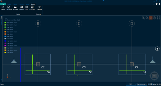
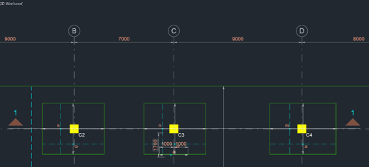
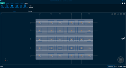 View of design strips along X direction
For detailing of flat slabs or foundations, the common design approach is to use the Mesh + extra rebar method. In this method, the design cubes formed for a given direction on a given surface are considered together, which would cover all the geometry. Design for top rebar in X direction is for a completely different set of cubes than for the bottom rebar in X-direction. The level difference created between various parts of mat (or slab) due to variation in thickness or top of concrete are effectively captured in detailing.
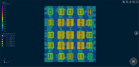
View of AST-required for Mat.
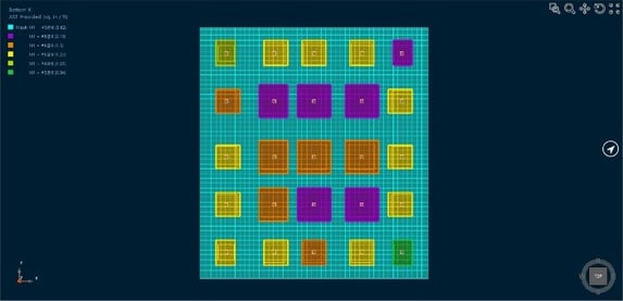
View of Ast-provided for Mat.
Mesh + extra rebar method of detailing – In this method, there is generally a rebar diameter-spacing combination called “mesh” which is provided throughout the slab in a given direction. In the areas where this mesh does not satisfy the design requirement, then extra rebars are provided to satisfy the total requirement. This method lends itself to ease of construction, since rebars are provided throughout. Extra rebars are provided only in pockets. Users can control the overall optimization of mesh and extra rebars by appropriate settings for “mesh coverage.”
 Rebar detail view (software)
Rebar details (drawing)
Drawing and Reports Generation
RCDC - FE can generate ready-to-ship drawings after detailing is completed. Users can mark the locations of sections using appropriate tools. They can also provide customized anchorage details for various types of rebars. Many types of drawings can be generated, including:
- General arrangement drawing for plan
- In-plan detailing of top and bottom rebars with legend for each rebar type
- General arrangement sections at specified locations
- Detailed sections with rebars at specified locations
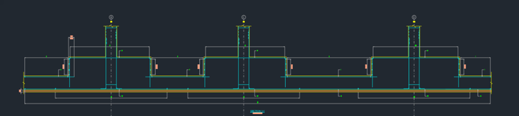 Detailed section through mat foundation with thickened regions
Various design reports are also available from RCDC - FE, such as:
- Detailed calculations for flexure for each “zone” with extra rebar.
- Punching shear calculations for columns, regions, and piles.
- Design summary for all flexural and punching checks for the critical load combination.
- Crack-width check report.
- Tabular report for flexure and punching for all load combinations with key values.
- Failure diagnostic report – This report tabulates all the locations and types of “design failure.” The user can evaluate probable causes and take corrective actions.
- Detailed BOQ is available for rebars, concrete and formwork.
STAAD Foundation Advanced provides many reports, including:
- Results of stability checks – Sliding and overturning.
- Maximum soil pressure from among all service and ultimate load cases.
- Contact area report for all load cases.
- Pile reactions report for all load cases.
- Soil settlement report for all load cases from the mat FE model.
- Punching shear report for the critical load case for each column.
- Flexure design summary report for longitudinal and transverse directions for both surfaces.
User Model
Here is a thumbnail view of a STAAD Foundation Advanced model of a mat foundation on piles supporting storage tanks in an industrial complex. The tanks were modeled using plate and solid elements with fixed supports in STAAD.Pro, and the reactions were imported into STAAD Foundation Advanced as loads on the mat. This model is shared by one of our long-time users, Aswathanarayana & Eswara LLP.
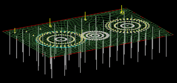 STAAD Foundation Advanced model of a mat foundation on piles supporting storage tanks in an industrial complex. Image courtesy Aswathanarayana & Eswara LLP.
Learn more about STAAD and RAM with Virtuosity:
Attend the webinar series: Register here
Discover the Reinforced Concrete Design with STAAD and RAM series featuring blogs and webinars
Read this success story on "San Diego’s Largest Apartment Complex" to see how DCI Engineers used STAAD and RAM software
For the price and the amount of Keys included in RAM Virtuoso Subscription, please visit this page.
Want to learn more about what STAAD and RAM can do for you? Don't hesitate to contact our structural experts. We are happy to help.