In a pipe network, all elements are connected such that changing anything at any location impacts the entire network.
Adding a pipe in the far northwest part of the system affects flow in the far southeast part (minimally in many cases). The right way to model any pipe network is to include all elements that affect the behavior of the network.
In many cases, it is possible to skeletonize a network by removing/combining elements that don’t have much impact. In other cases, it may be possible to model parts of the system separately, such as pressure zones, provided that the boundaries between these zones are well-defined.
Problems become complicated when parts of an overall water system cover multiple entities such as:
- Upstream water utility A providing water to downstream utility B
- Upstream water utility A providing water to large downstream land development B
The Right Way
The “right way” to perform the hydraulic analysis is to have a single hydraulic model that encompasses both the upstream and downstream systems into a single pipe network model. Once this model is constructed, analysis of the two systems can account for complex interactions between the systems.
However, building a single unified hydraulic model between entities isn’t always feasible for a variety of reasons. The upstream system may not want to share its model with the downstream system. The downstream system’s engineers may not want to deal with the complexities of the upstream system, or the downstream system’s owner may not want to pay the engineers to build a unified model.
However, the fact is that head loss and flow in the upstream system do affect the performance of the downstream system. Over the years, engineers have evolved approaches to deal with the complexities of connecting two systems. There is no single “best way” to simplify the pipe network. The analysis depends on the relative sizes of the systems, the number of connection points, whether the downstream system is an existing or proposed system, the location and hydraulic grade of existing and proposed storage tanks, and the contractual service agreements between the systems. Some alternative approaches are discussed in the following sections:
Single HGL
Engineers for the downstream system would like to know a single value for the hydraulic grade line (HGL) (or pressure) at a connection point. This may be true in certain situations where the connection point is located near a tank, and it is connected to the connection point with a large enough pipe that there is a negligible head loss in the upstream system. This is rarely the case as usually there is some non-trivial head loss between the sources of supply or storage in the upstream system and the connection point. Even if the HGL appears to be relatively steady most of the time, the supply must also work during a fire, emergency, or other peak demand time. While this approach of approximating the upstream systems as a single constant head node involves the least amount of work for the downstream system’s engineer, it is the least accurate. It may be acceptable if the downstream system’s demands have a negligible impact on the upstream system.
Fire Flow Test Approximation (Single Connection)
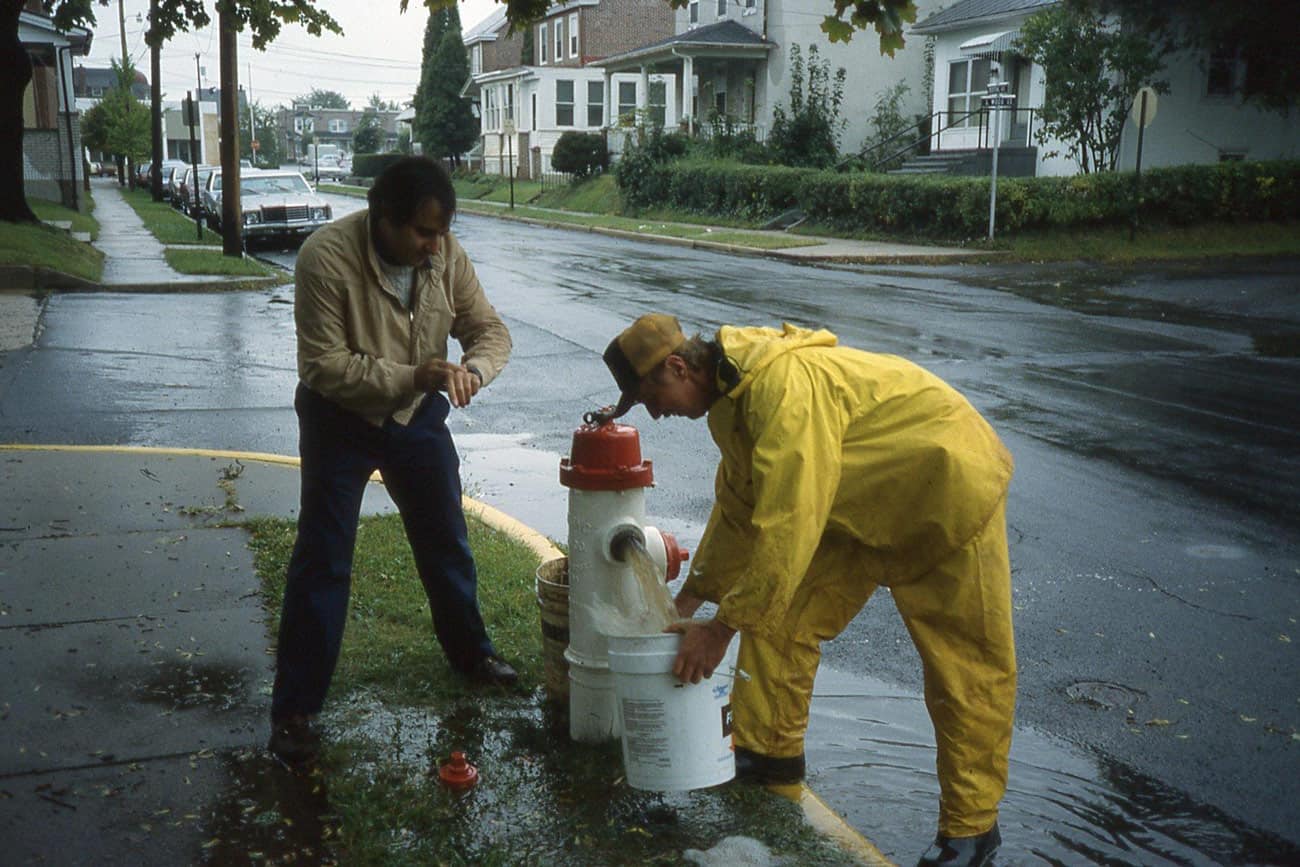
Ideally, the engineer for the downstream system needs to know how the HGL at the connection point varies over the range of demands expected. The most straightforward way to look at the relationship between the demands and the HGL is to conduct a hydrant flow test at the connection point. This can produce a table of hydrant flow vs. residual pressure (and HGL).
The curve relating the hydrant flow to the pressure head has the same general shape as a pump head curve. Using that data, it is possible to replace the existing upstream system with a reservoir element located at the elevation of the flow test’s residual pressure gage and a pump with a pump head curve corresponding to the head vs. flow relationship determined during the flow test. This is shown graphically in the figure below.
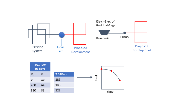
Usually when running a hydrant flow test, a single flow and its associated residual pressure are measured. To get a smoother equivalent pump curve, it is helpful to record residual pressure at several different hydrant flow rates.
This approach is built on several assumptions including:
- The behavior of the upstream system during the flow test is sufficiently representative that it can be used as the basis for the connection point,
- Future changes to the upstream system will not adversely impact the results,
- There is only a single connection point.
If these assumptions are valid, then more accurate methods may be required.
There is a nice wiki article under Bentley Communities that provides more details about this approach.
Fire Flow Test Approximation (Multiple Connections)
If there are multiple connections between upstream and downstream systems, the interactions between the connection points must be accounted for. In this case, multiple individual flow tests cannot be used, but instead, there would need to be a single flow test where hydrants adjacent to all connections are flowed at once to account for the fact that more flow at on hydrant will correspond to less as others.
Simultaneously flowing multiple hydrants may have an adverse impact on the pressures in the upstream system. This would indicate that the upstream system may have difficulty providing the desired flow to the downstream system without improvements.
If there are multiple connections where the supply from the upstream system comes from different pressure zones, then it may be acceptable to conduct separate flow tests from each pressure zone.
Simulated Fire Flow Tests
If the modelers in the upstream system are agreeable, they can run their hydraulic model to simulate static and fire flow conditions to provide the engineer for the downstream system with information needed to generate the curve(s) used to simulate the head loss in the upstream system. It‘s assumed that the upstream system model has been calibrated well for the connection point location.
An advantage of using hydraulic model simulations is that it is possible for the modelers to simulate any boundary condition that they want, such as changing pump status, tank water levels, or control valve settings. When using an actual hydrant flow test, the person conducting the test can only accept whatever conditions exist at the time of the test. With a model, it is also possible to investigate the impacts of potential or proposed system improvements on the supply to the downstream system. For example, the upstream system may be designing a proposed tank that will markedly improve flow to the downstream system.
Skeletal Model
Instead of relying on the equivalent pump approach to estimate the flow vs. available pressure curve, the engineer for the downstream system can get a copy of a map or GIS of the upstream system. With that information, the engineer can construct a skeletonized model of the upstream system containing only the most important tanks, pumps, and pipes serving the connection point.
Such a model would need to be calibrated using data collected from a fire hydrant flow test as close to the connection point as possible. It is essential that such a skeletal model match the residual HGL both for the static and flow conditions. It’s also very helpful to exactly know the state of the upstream system during the flow test. What pumps were running, what was the water level in the tanks and what was the setting on any PRVs feeding the zone as these can all be varied in the upstream system?
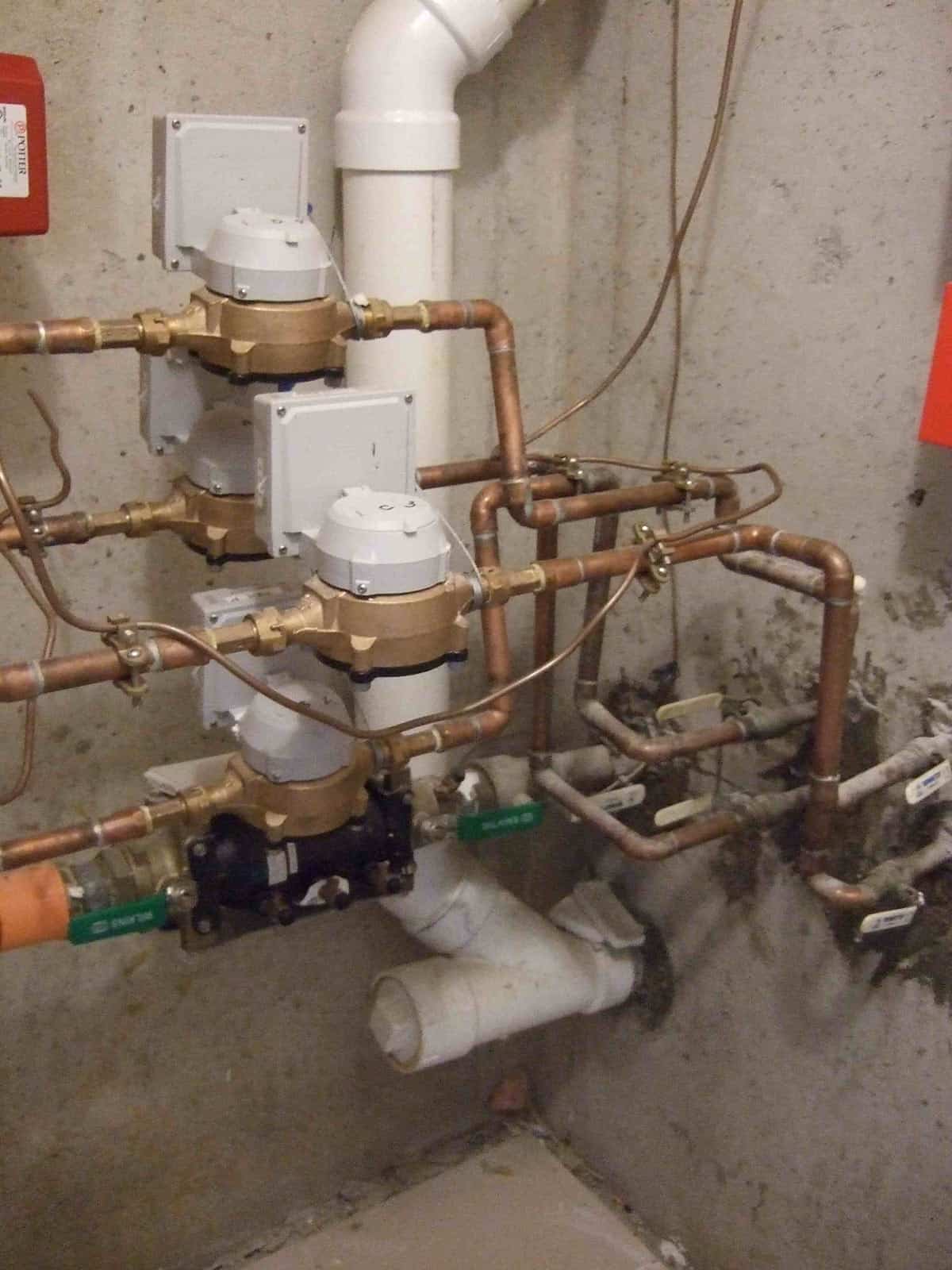
For this model and any of the simplified modeling approximations, it is also important to know the configuration of the connection point. Flowmeters, control valves, and backflow prevention can increase the amount of head loss at the connection.
Skeletonizing Upstream System
In some cases, the upstream system may be willing to provide a copy of its model. However, the engineer for the downstream system may not want to deal with a very large, complex model, or the upstream model may contain 20,000 pipes while the downstream engineer may have a 5000-pipe license. While the best solution may be to upgrade the license, it may be possible to reduce the size of the upstream system model by removing pressure zones that have no impact on the downstream connection and skeletonize the upstream model, either manually or using WaterGEMS’ Skelebrator tool. In most cases, many small pipes carrying very little flow can be eliminated without seriously affecting model accuracy. Nevertheless, if the model is skeletonized, the calibration needs to be verified over a range of conditions because reducing the model size may affect its accuracy.
Service Agreement
Most connections like this will be governed by some type of service agreement. The downstream system’s engineer needs to understand the details of this agreement.
For example, the agreement may state that the upstream system will provide 700 gpm to the downstream system. Does that mean they will provide:
- 700 gpm continuously,
- 700 gpm average across the day (e.g. 2800 for 6 hours and 0 for the rest of the day),
- Not to exceed 700 gpm with an average delivery of 250 gpm,
- A minimum of 700 gpm with the ability to supply additional water during fires and other emergencies.
Will there be any type of control valve that will prevent the downstream system from taking too much water? For example, a pressure sustaining valve may throttle the flow if the upstream system’s pressure drops below 35 psi.
Some of these considerations will depend on whether the connection is:
- The sole source for the downstream system,
- A major source for the downstream system,
- A backup source for the downstream system.
Summary
When multiple water systems are connected, they form a single pipe network, and the best way to model such a network is with a single comprehensive model. As discussed above, this isn’t always feasible. The article discussed some of the options for such a situation with recommendations and limitations for each approach. Get several readings of flow vs. residual pressure and provide a smoother pump curve.