Author: Hamzah M. B. Al-Hashemi, M.Sc., A.M.ASCE
Sr. Geotechnical Design Engineer at Strong Force-MGC W.L.L., Bahrain
Visiting Lecturer at University of Bahrain
The manual, semi-manual, and 2D (FEM/LEM) design methods for various Geotechnical & Geostructural problems are usually preferred by a wide range of practicing engineers owing to their simplicity & quick calculations. It was believed that these methods usually tend to be over-conservative and practical. While this might be the case for some projects, the generalization of this hypothesis is questionable and should be evaluated on a project-to-project basis.
One of the crucial problems where the 2D-versus-3D argument is valid; is the shoring support for deep excavation. Therefore, this article aims to employ a real-life case study from one of our projects in Bahrain, mainly to clarify the below doubts:
- Are the semi-manual or 2D design methods always applicable?
- If yes, are they the most conservative and/or economical?
Case Study
Our client has approached us to provide a shoring support solution for their project on a design-and-built basis. The project consists of a high-rise structure with deep excavations in some areas. The area of interest in this article is the roundabout. The shoring system installed at the roundabout area is a tangent piling wall (TPW), consists of piles with 830mm Dia., and ~ 15m deep, each, to support ~ 9m of deep excavation in a silty SAND layer followed by a weak SILTSTONE layer. The GWT is @ 2m begl. The case is depicted in Figure 1 below: 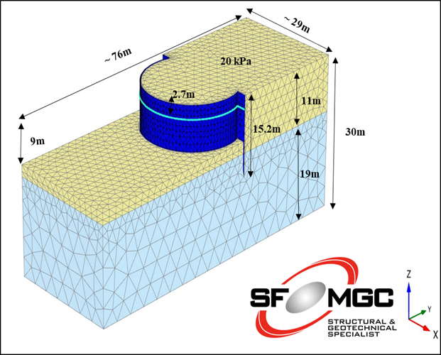
Figure 1: Sketch of the Case Study
Initial Design
The client provided us with an in-hand 2D design from an independent designer for the shoring support system. The 2D design covers two areas; a straight roadside and the roundabout side. Of course, the design of both the areas was identical. The proposed supporting system for the TPW at the roundabout side is 39 nos. of uniform single-level Ground anchors with 1.7m spacing, 20 degrees inclination, at 2.7m level & 15m total length, refer to Figure 2. 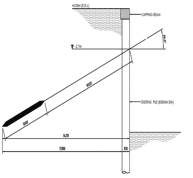
Figure 1: Sketch of the Case Study
Limitation of the Initial Design
The provided 2D design has failed to address the actual 3D nature of the project (the curve of the roundabout side) because the 2D design assumed that the TPW is straight and continuous in the out-of-plane direction. However, the reality shows that all the proposed ground anchors are clashing & intersecting at one point, affecting their functionality, refer to Figure 3. Therefore, the provided design might be safe and valid only on paper!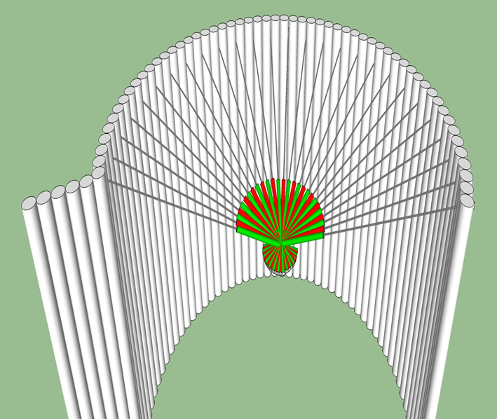
Figure 3: Clashing of the Anchors in the Initial Design
PLAXIS 3D Model
With the above-mentioned limitations in mind, we have decided to utilize PLAXIS 3D to analyze and design this case. The conceptual design is brain-stormed on papers, followed by the 3D drawings & sketches developed by our draughtsmen. The main idea was to manipulate the ground anchors arrangement in terms of various inclination, spacing, and lengths so the anchors will not intersect or affect each other. Different soil models have been used (LE, MC, HS, HSS & GHS) for the sand, rock, and TPW materials covering the expected range of their properties (i.e., sensitivity analysis).
The model's size, quality of the mesh, boundary conditions, water flow regimes, and permeability of the system (fully permeable, impermeable, semi-permeable) are considered in the analysis. Moreover, the TPW was modeled as LE & elastoplastic equivalent plate element (which took less than an hour to analyze), as well as MC volume piles elements using soil clusters to represent the granular details of the actual scenario (which took a couple of days on an overclocked CPU needed to analyze ~ 3 millions of nodes). The complexity, simplicity, and details included in the model is the designer's decision based on time, accuracy, and cost factors. No worries! The TPW modeled as a correct equivalent plate element might be sufficient if you wonder.
The TPW modeled as a plate element might be enhanced by considering the custom connections between the plate panels and the expected water flow through the TPW using the interface permeabilities feature. Nonetheless, one of the major advantages of using plate elements is the straightforwardness of getting the structural forces acting on the TPW.
The final ground anchors arrangement is shown in Figure 4. The maximum deformation of the TPW was < 30mm, comparable between the plate and volume elements, refer to Figure 5. Finally, the worst-case global factor of safety determined in PLAXIS 3D for the whole elastoplastic system is found satisfactory (~ 2.0), and the slip surface is shown in Figure 6. 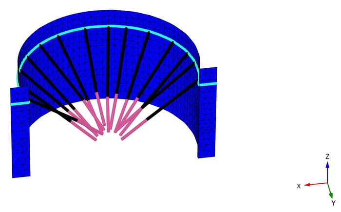
Figure 4: Final Ground Anchors Arrangement in PLAXIS 3D
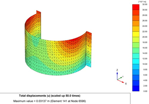
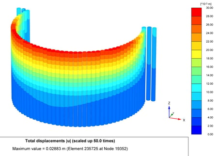
Figure 5: Deformation Pattern of the TPW as (a) Plate Elements and (b) Volume Elements
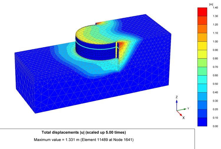
Figure 6: Slip Surface from the Safety Analysis Conducted in PLAXIS 3D
Conclusion
The design conducted using Plaxis 3D resulted in reduced anchors of only 16 nos., workable, safe, and not clashing with each other considering all SSI's. The total savings in cost and time is ~ 58%. Therefore, no, 2D designs are not always applicable or the most economical.
"Some projects are 3D in nature and, therefore, require 3D designs to provide appropriate, safe & value-engineering solutions. Hence, PLAXIS 3D is a game-changing tool that helped us to secure such projects."
Discover more about 2D-versus-3D analysis in this article: https://blog.virtuosity.com/why-run-plaxis-3d-analysis