At least for water piping, air bubbles are comprised of nitrogen and oxygen, and other gases, just like air, while cavitation is caused by the water actually vaporizing.
Now that we understand that basic point, why would water vaporize in a pipe or pump? The overarching answer is that the pressure of the water at that point is less than the vapor pressure of water for that temperature. The two primary reasons are:
- A low-pressure wave caused by a hydraulic transient has passed through this location.
- A pump is pulling water into its impeller, but this lowers the pressure too much.
Both can cause problems, and both can be managed.
Transient Cavitation
Whenever the momentum of fluid changes, it generates transient pressure waves. If the change is large enough over a short enough period of time, the resulting wave can lower the pressure to below vapor pressure, and the water will vaporize. This usually occurs at high points along the pipe since the pressure is already low there.
The cavitation itself doesn’t affect the pipe, but it forms an expanding water vapor pocket moving away from that high point in what’s called “column separation.” That doesn’t hurt the pipe either. Eventually, however, the pressure exceeds vapor pressure starting at each end of the separation. The water condenses, and two water columns crash into one another like two high-speed trains colliding. The pressure skyrockets and pipes burst or pop out of the ground—the bigger the pipe, the worse the calamity.
The best solution is not to change the momentum of the water quickly. But sometimes valves are operated too fast, or a power loss at a pump station quickly changes the momentum resulting in a transient. Operator training, pump control valves, soft starts, and variable speed drives can lessen the likelihood of this occurring.
Once a transient has been released on the system, it can be controlled by pressurized and open surge tanks, vacuum breaker valves, and surge anticipator valves, among other devices. These devices attempt to prevent or control the pressure drop that leads to cavitation.
An OpenFlows HAMMER model can help identify where and how the pressure drops can occur and help design the needed control measures.
Cavitation in Pumps
Centrifugal pumps are great at pushing water through a pipe. They aren’t as proficient at sucking water through a pipe. As a pump pulls water into its impeller, it lowers the pressure. If the pressure is sufficiently low, the water vaporizes. This creates small pockets of water vapor that form and quickly collapse as the pressure increases. This formation and collapse of vapor pockets damage the impeller over time. The picture below shows what an impeller can look like after a few years of this damage.
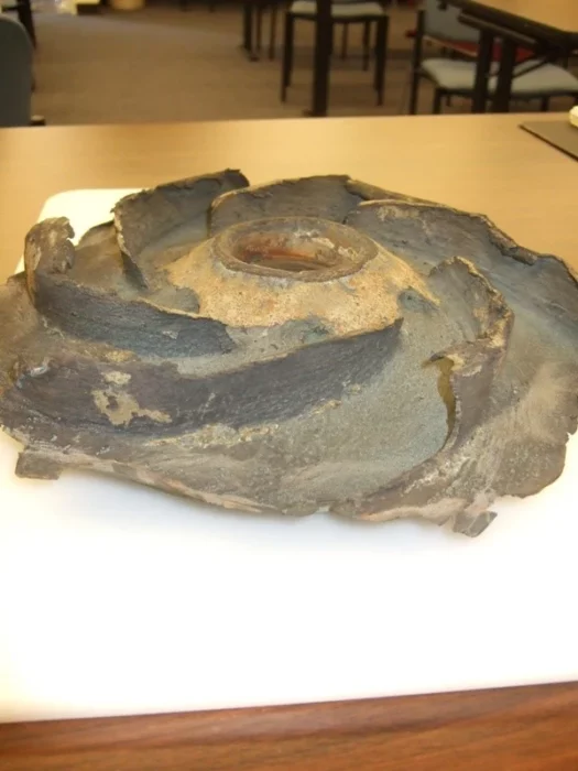
The cause of this lies in the design of the pump impeller and its need for a sufficient suction head. If the pump is at too high of an elevation relative to the available hydraulic grade or there is excessive head loss in the suction piping, cavitation can occur.
The key property determining when cavitation will occur is the net positive suction head (NPSH). The NPSH (required) is a property of the pump and can be found in the pump characteristic curves supplied by the manufacturer. The system determines the NPSH (available). This can be calculated or measured. OpenFlows WaterGEMS can automatically determine NPSH(available). Once NPSH(Avail) < NPSH(Req), cavitation is likely to occur.
Good pump selection and piping design should ensure that cavitation is avoided. If it occurs, the pump will tell you there is a problem. The collapse of cavitation bubbles sounds as if gravel is being passed through the pump.
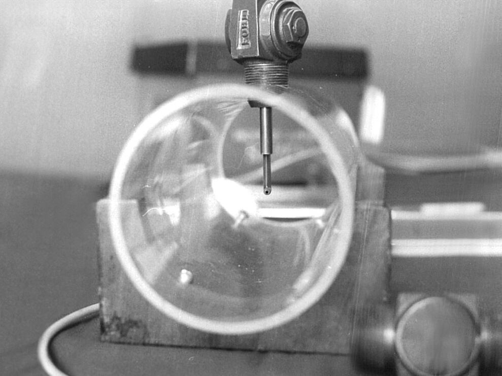
When I was a young engineer, I was involved in a research study where we built a “cavitation machine” to test cavitation effects on various materials. By adjusting the right valves, we could cause any level of cavitation we wanted. When we maximized cavitation, the vapor pocket collapse sounded like a jet engine.
As the flow through a pump increases, the NPSH(req) increases, and NPSH(avail) decreases, which can cause cavitation to occur only at high flow rates. For example, the problem can occur only when an additional pump turns on, and a common suction line has increased head loss.
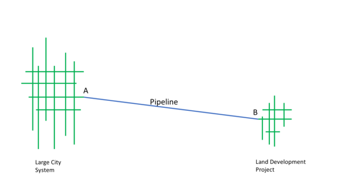
I was involved in one modeling study when a large city system served a land development several miles from the end of the city system. They needed a pump to provide sufficient flow and pressure for the project. They should have placed the pump in location A in the figure below, but they placed it at location B. The head loss between A and B reduced the NPSH (avail) to the point where cavitation eventually damaged the pump so that it no longer performed per its head characteristic curve. When they replaced the impeller with a new one, the model agreed with the field pressure, but they still needed to solve the cavitation problem.
OpenFlows WaterGEMS and OpenFlows HAMMER provide the tools to help you prevent and control cavitation.