The Challenge in Slope Stability Analysis for Embankments on Clay
The construction of an embankment on clay can generate excess pore pressure in the clay, causing slope stability problems in the short term. For this reason, it’s important to evaluate the Factor of Safety while considering the clay behavior both drained (long term) and undrained (short term). These different Factors of Safety can be easily determined using finite element software to perform a strength reduction safety analysis.
Slope Stability Analysis Made Simple
For a finite element analysis of an embankment on clay, the required inputs are as follows:
- Soil stratigraphy
- Embankment geometry
- Geotechnical parameters of the materials involved
These parameters vary according to the constitutive model adopted for each material. Here are some example models:
- Young's Modulus and Poisson Ratio for stiffness
- Cohesion for strength, unit weight, etc.
The workflow to perform your finite element analysis would follow these steps:
- Define the soil stratigraphy
- Draw the structures related to the geotechnical project
- Create the Finite Element mesh
- Define the flow conditions
- Set the staged construction phases
After these steps are completed, the geotechnical analysis can be performed. Each construction phase is calculated separately, in sequence.
Breakdown: Example Analysis
As an example, we’ll consider a 13 ft (4 m) high embankment.
- The slopes are 1V:2H and 1V:3H constructed on a clay foundation
- The embankment crest width is 7 ft (2 m)
- The groundwater level is at the surface
- Two different sets of parameters are defined for the clay foundation: one for the drained behavior and the other for the undrained behavior
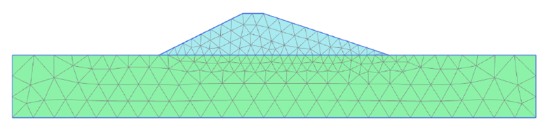
Geotechnical model of the slope stability example
To analyze the drained and the undrained stability of the problem, different calculation phases are set:
Initial phase: Generation of initial stresses at the site, prior to the construction of the embankment. Due to the horizontal surface, the K0 procedure can be used to do so.
First phase: Plastic calculation of the construction of the embankment on the drained clay.
Second phase: Plastic calculation of the embankment on undrained clay.
For the strength reduction safety analysis, two new phases are created: the third phase, starting from the first phase, for the drained safety analysis, and the fourth phase, starting from the second phase, for the undrained safety analysis.
The output of the finite element analysis of the phases above is the strain, displacements, stresses, pore pressures, and Factor of Safety for both the drained and undrained foundation. The failure mechanism can also be seen for both cases.
For example, the displacements indicate that the embankment settles everywhere in the case of the drained foundation, while in the undrained case the foundation heaves near the toes. This makes perfect sense: it cannot be volume change in the undrained foundation. Hence, if the subsoil settles in the middle due to the weight of the embankment it must heave somewhere else, typically just next to the embankment.
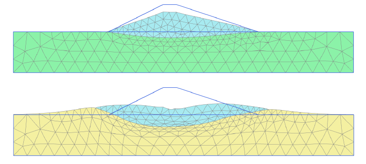
Deformed mesh after drained (top) and undrained (bottom) plastic calculation
Regarding the generation of excess pore pressures, we see that no excess pore pressure is generated in the drained condition, as expected. For the undrained condition, the location, intensity, and principal directions of the excess pore pressure can be verified. For example, we can see that the highest values of pore pressure occur directly underneath the embankment.
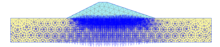
Excess pore pressures after construction on undrained subsoil
The obtained Factors of Safety are different for the drained and undrained analysis, showing the effect of the excess pore pressure in the foundation. The maximum displacements presented in the safety analysis have no physical meaning, as they depend on the number of steps. More loads steps would mean the calculation would push further into failure, thus generating larger displacement – while, in reality, a failing embankment would re-establish a new equilibrium with limited deformations. However, the incremental displacements in the final step of the calculation are very useful as they give an indication of the likely failure mechanism.
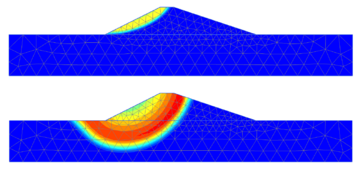
Failure mechanism after drained (top) and undrained (bottom) analysis
The failure mechanisms indicated by the safety analysis show that with drained foundation, the critical slip surface is located completely within the embankment. On the other hand, with undrained foundation, the critical slip surface also passes through the foundation.
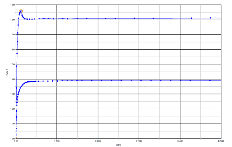
Evaluation of the Factor of Safety, drained (top) and undrained (bottom)
This example shows how finite element analysis is a powerful tool to evaluate the generation of excess pore pressures and Factor of Safety, providing important information to assess the compliance with safety standards of geotechnical projects.
Want to see an example in action? Watch the recording of our Level up Your Geotechnical Workflow webinar, available on demand.