The Challenge in Urban Excavation Analysis
Vertical excavations are common in urban environments due to the lack of available space for gentle slopes. These excavations are supported by retaining structures, such as diaphragm walls tied back by prestressed ground anchors, that need to be properly designed. Finite element analysis allows for detailed modeling of this type of scenario, including the effect of anchors and prestressing on the force distribution in the diaphragm wall and the effect of lowering the water table on the soil stresses and surface displacement.
To design an urban excavation, a geotechnical engineer must determine
- the displacement caused on the surface around the excavation,
- the forces on the retaining structure for a proper structural design, and
- the effect of the prestressed anchor and lowering the water table on the surface displacement and on the retaining structure.
Urban Excavation Analysis Made Simple
Finite element analysis (sometimes referred to as FEA) can be used to determine these necessary factors. Here we break down the basic workflow to use the finite element method (FEM) for urban excavation analysis.
For this analysis, the required inputs are as follows:
- Soil stratigraphy
- Excavation geometry
- Construction stages over time
- Stiffness, resistance and flow parameters of the materials involved
These parameters vary according to the constitutive model adopted for each material. Here are some example models:
- Young's Modulus and Poisson Ratio to describe soil stiffness
- Cohesion and Friction Angle to describe soil resistance
- Saturated Permeability as a soil flow parameter
- Axial and Bending Stiffness to describe the retaining structure's mechanical behavior
- Axial Stiffness for the anchor rod
The workflow to perform your finite element analysis would follow these steps:
- Define the soil stratigraphy
- Draw the structures related to the geotechnical project
- Create the finite element mesh
- Define the flow conditions
- Set the staged construction phases
After these steps are completed, the geotechnical analysis can be performed. Each construction phase is calculated separately, in sequence.
Breakdown: Example Analysis
As an example, we’ll consider an urban excavation that’s 65 ft (20 m) wide and 33 ft (10 m) deep.
- It has 52 ft (16 m) long diaphragm walls that are 1 ft (0.3 m) thick and used to retain the surrounding soil
- Two rows of anchors are installed at each wall. The anchors have a total length of 48 ft (14.5 m) and an inclination of 33.7o
- Surrounding the excavation, there is a surface load of 200 lbf/ft2 (10 kN/m2)
- The soil stratigraphy consists of three distinct layers. From the ground surface to a depth of 10 ft (3 ms) there is silt. From 10 ft (3 m) to 50 ft (15 m) depth there is sand. Below the sand, there is loam.
The phases of the staged construction are set as follows:
Initial phase: Generation of initial stresses at the site, prior to the construction of the embankment. Due to the horizontal surface and horizontal layering, the K0 procedure can be used to do so.
First phase: Activation of the surface load and the installation of the wall.
Second phase: Excavation of the first 10 ft (3 m).
Third phase: Installation of the first row of prestressed anchors.
Fourth phase: Excavation from 10 ft (3 m) to 23 ft (7 m) depth.
Fifth phase: Installation of the second row of prestressed anchors.
Sixth phase: 10 ft (3 m) lowering of the water table and excavation from 23 ft (7 m) to 33 ft (10 m) depth.
After setting the staged construction phases, the calculation can be done.
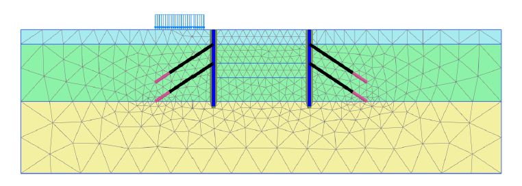
Geotechnical model of the urban excavation example
The output of this finite element analysis is the strains, displacements, stresses, and pore pressures within the soil and forces on the structural elements for each of the phases. For example, the maximum settlement around the excavation can be verified to comply with design requirements. Moment, shear, and axial forces of the diaphragm wall can be determined. Graphs showing the envelope of maximum moment or shear force in the structural element along all phases can also be drawn.
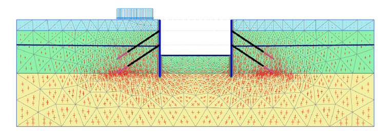
Principal effective stresses, final phase
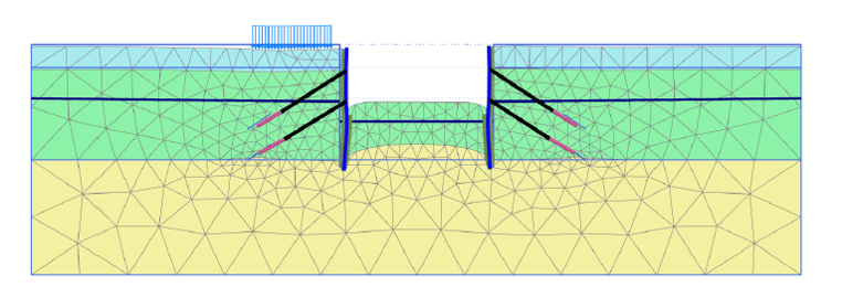
Deformed mesh (scaled up 50 times), final phase
Finite element analysis can be used to estimate the settlements that will occur around an urban excavation and assess compliance with local requirements. Furthermore, it serves to optimize the design of geotechnical structural elements, such as retaining walls, plates, and anchors, in regards to their dimensions and spacing.
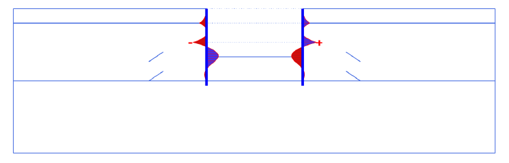
Bending moments in the diaphragm walls in the final phase
Want to see an example in action? Watch the recording of our Level up Your Geotechnical Workflow webinar, available on demand.