Authors
Marco Candela, M.Sc.
Project Manager at Geodata Engineering S.p.A, Turin (Italy)
Lorenzo Gorlier, M.Sc.
Design Manager at Geodata Engineering S.p.A, Turin (Italy)
Cristiano Bertello, M.Sc.
Geotechnical and Tunnel Engineer at Geodata Engineering S.p.A, Turin (Italy)
Luca Rosa, M.Sc.
Geotechnical and Tunnel Engineer at Geodata Engineering S.p.A, Turin (Italy)
With the largest economy per capita in the Middle East. In recent years, the increasing demand for improved mobility has resulted in the fast-tracked development of the city’s mass transit system.
The proposed system includes three metro lines (M1, M2, and M3) and three light rail lines (Red, Green, and Purple). The Green Line is a light rail project that belongs to the mass transit network.
In this article, the main aspects concerning two underground stations belonging to this project will be presented as case studies, focusing on the 2D numerical analyses performed with the Finite Element Method-based software PLAXIS 2D (Bentley Systems, Inc.).
The aim of this article is to demonstrate the suitability of 2D FEM analyses in metro station outer boxes structural element design (even in demanding conditions) with specific reference to the Arlozorov West Station and Rabin Station.
The Green Line Project
The Green Line is a light rail line that will connect the southern portions of the Gush Dan metropolitan area. It represents one of the main solutions for mobility development along the Mediterranean coast, facilitating accessibility to university and production areas.
The light rail line will have a length of approximately 39km (4.5km underground) and 62 stations of which four are located underground. Two of them are the ones that will be presented in the following as case studies.
Arlozorov West Station
The Arlozorov West Station has an outer box dimension of about 23m x 197m with a depth of approximately 27m. The excavation will be performed with the cut and cover technique, and the permanent structures of the station will follow the bottom-up construction procedures. The diaphragm walls reach the depth of -40m a.s.l. and their thickness is 1.2/1.5 meters. Four levels of steel struts are designed as a support system: circular hollow profiles with a diameter of 914/1219mm and thickness 16/25mm spaced 3/5m. The standard cross section is completed by a temporary concrete slab at bottom excavation level (200cm thick) and a steel truss structure at ground level that acts as a deck to ensure the urban road system operativity during the construction activities (Figure 1).
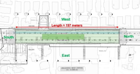
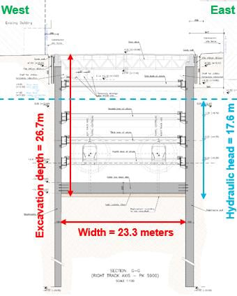
Figure 1: Plan view and standard cross section (Arlozorov West Station)
The vicinity of the station is characterized by the presence of retaining walls, low building (four floors), towers (existing and under construction), and station entrances (Figure 2).
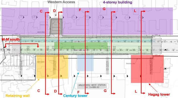
Figure 2: Sections analyzed and vicinity of Arlozorov West Station
The following paragraphs present the analysis of section L-L (refer to Figure 2), located between 4-story buildings in the west side and the future Hagag Tower on the east side (currently only the excavation of the tower’s underground floors and its foundations have been executed). The distance between the future tower and the station is 7.5m, and the foundation of the building reaches -7.40m a.s.l. (about 17.5m from surface).
Geological and hydrogeological conditions are coherent with results of the investigations performed in the area: the geology is mainly characterized by stiff and calcareous sand and the Hardening Soil Model has been used in the analyses to provide reliable results in terms of deformations. Groundwater table during construction period is located at +1.5m a.s.l., approximately 9m below ground level.
Different structural elements have been used in the model (PLAXIS 2D – Reference manual), to represent the concrete diaphragm wall and slab structures (plate elements) and steel elements (i.e., struts and steel deck modeled with node-to-node anchors).
The PLAXIS 2D model described above is reported in Figure 3.
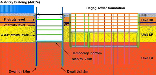
Figure 3: PLAXIS 2D model (Arlozorov West Station).
The construction sequence considered in the model can be summarized as follows:
- Application of existing load on west side of the station
- Excavation of the first part of the Hagag Tower foundation (bottom-up method)
- Excavation of the second part of the Hagag Tower foundation (top-down method)
- Diaphragm walls installation
- First step of station excavation and subsequent steel deck installation
- Activation of dewatering system
- Steps of station excavation and installation of four levels of steel struts
- Installation of the temporary concrete bottom slab and deactivation of dewatering
- Deactivation of the fourth strut level to allow space for TBM passage through the station
- Simulation of inner box construction and deactivation of steel struts and deck
Particular attention was paid in the simulation of the dewatering system. In fact, it is defined by applying two vertical drainage elements in the model. Activated in the first steps of the calculation, drains have been simulated by setting different water head values to the drainage elements in the model consistently with the excavation phases. After the temporary concrete bottom slab installation, these elements are deactivated, and the water table is restored to the original level. Figure 4 depicts the layout of drainage elements and water table height for the last excavation stage, with the related output showing groundwater flow vectors of the steady state flow analysis.
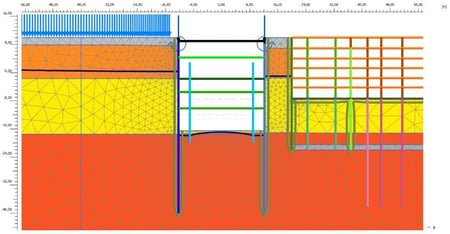
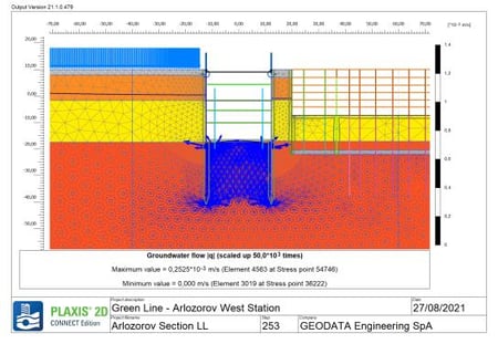
Figure 4: Simulation of dewatering system (Arlozorov West Station).
The numerical model performed allowed the team to compute the envelopes of bending moment and shear forces in the diaphragm walls (Figure 5), from which it was possible to perform the structural verifications (Figure 6).
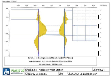
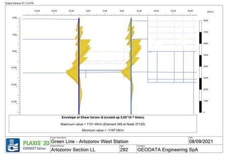
Figure 5: Envelopes of bending moments and shear forces in diaphragm walls (Arlozorov West Station).
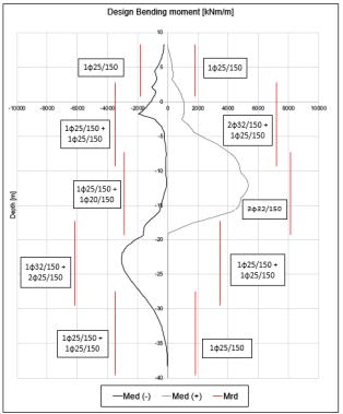
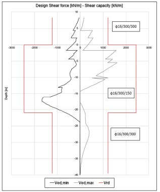
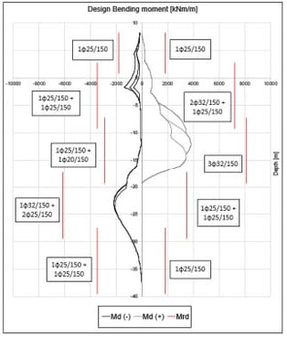
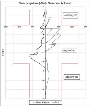
Figure 6: Diaphragm walls structural verification (Arlozorov West Station).
The numerical model described above even allowed the team to perform the structural verifications of the circular hollow struts, after computation of maximum axial forces in the elements (Figure 7).
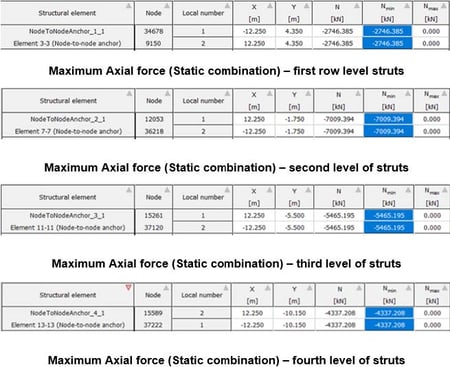
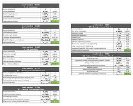
Figure 7: Axial forces (left) and structural verifications (right) of circular hollow struts (Arlozorov West Station).
Rabin Station
The Rabin Station has an outer box dimension of about 23m x 173m with a depth of approximately 22m. The excavation method is the cut and cover technique, and the inner box will be constructed by means of the bottom-up method. The diaphragm walls in this case reach the depth of -32m a.s.l. and their thickness is 1.2m on the west side and 1.5 meters on the east. In Rabin station, three levels of steel struts are foreseen as a support system:
- The first level has profiles with diameter of 1219 mm and 25 mm thickness.
- The second has profiles with diameter of 1219 mm and thickness of 20mm.
- The third, divided in two typologies, at the northern side has profiles with diameter of 1016 mm and 20mm of thickness while in the southern side with diameter of 1219 mm and 20mm thickness.
The standard cross section (Figure 8) is again completed by a temporary concrete slab at the bottom excavation level (80cm thick) and similar steel truss structure at ground level, with reference to the previous case study.
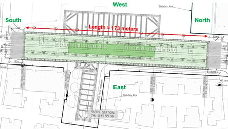
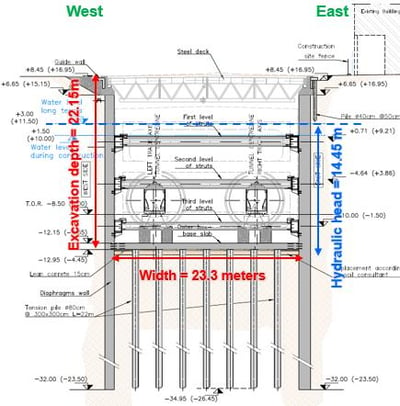
Figure 8: Plan view and standard cross section (Rabin Station).
In this case, the vicinity of the station is characterized by the presence of public squares, low buildings (with up to six floors) with different basement levels and large entrances, especially on the west side (Figure 9)
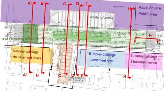
Figure 9: Sections analyzed and vicinity of Rabin Station.
The case study presented here refers to section A*-A* that is located in the southern portion of the station. At the east side, a six-story building without basement floors is present, while on the west side stands Rabin Square, an important public gathering area.
Geological and hydrogeological conditions are once again coherent with results of the investigations performed in the area. In this case, the geology is mainly characterized by calcareous sand, clayey sand to sandy clay. Thus, the Hardening Soil Model was chosen for the analyses. In addition, a thick clay layer is present in this area, whose depth is approximately located at the final excavation level of the station and reaches a depth larger than the D-wall toe levels. This configuration allowed the team to create a “sealed” excavation, reducing the dewatering volumes. The groundwater table during the construction period was located at +1.5m a.s.l., approx. 8m below ground level.
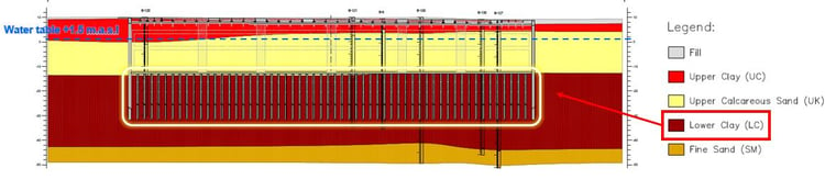
Figure 10: Longitudinal section (Rabin Station).
The various structural elements previously introduced for the Arlozorov West Station are confirmed even in this model, with the addition of an “embedded beams element” to simulate tension piles under the bottom slab of the station. These technological elements, also known as uplift piles or anchor piles, represent a type of pile foundation that is used to resist uplift forces. The tension piles have been designed to reduce the swelling pressure of the clay acting on the temporary bottom slab. They help reduce the excavation depth limiting the diaphragm wall deformations and ground settlements and, therefore, the impacts on adjacent buildings. A hinged connection between tension piles and bottom slab has been considered.
The PLAXIS 2D model described above is depicted in Figure 11.
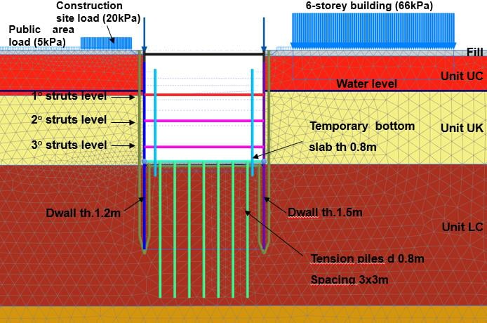
Figure 11: PLAXIS 2D model (Rabin Station)
The construction sequence considered in this model can be resumed as follows:
- Application of existing load on both the east and west sides of the station
- Initial consolidation to reset the displacements due to surcharge loads
- Installation of diaphragm walls and tension piles
- First step of station excavation and steel deck installation
- Activation of dewatering system
- Steps of station excavation and installation of three levels of steel struts
- Installation of the temporary concrete bottom slab and deactivation of the dewatering system
- Deactivation of the third struts level and simulation of TBM passing load
- Final consolidation after excavation works
- Simulation of inner box construction and deactivation of steel struts and deck
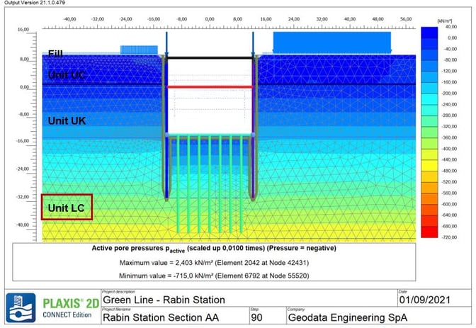
Similarly with the case of Arlozorov West Station, the dewatering system is defined through vertical drainage elements in PLAXIS 2D, and once again, the water head is set at different levels consistent with the excavation phases. After the installation of the concrete temporary bottom slab, the dewatering system is deactivated. However, the presence of the clay layer at the bottom of the excavation acts as a “plug,” generating excess pore pressures. For this reason, consolidation has been considered in the design. To define the stage in which the consolidation process had to be applied, evaluation of the consolidation time was performed. Due to the long consolidation time results, the calculation was performed once the final excavation condition was reached in the numerical model. Figure 12 shows the active pore pressures distribution after the consolidation stage.
By means of this modeling, it was possible to compute the information required by the design previously presented (envelopes of forces and bending moments, axial forces in steel elements). But in this particular case, other aspects, such as diaphragm walls and bottom slab deflections, are of particular interest (Figure 13).
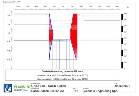
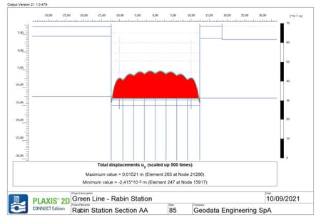
Figure 13: D-Walls horizontal deflections (left) and bottom slab vertical deflection (right) (Rabin Station).
Tension piles have even been checked and verified from the structural point of view. Figure 14 shows the envelopes of bending moment, axial, and shear force on these elements, while Figure 15 illustrates the structural verifications deriving from the numerical model results.
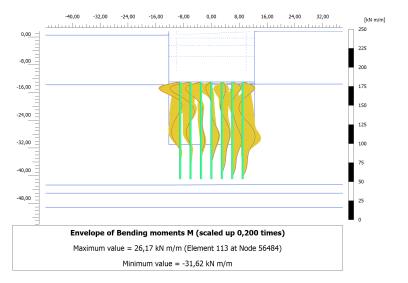
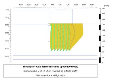
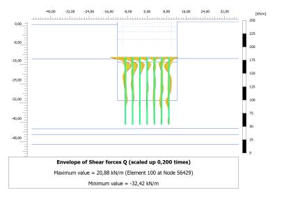
Figure 14: Tension piles bending moment, axial force, and shear force envelopes (Rabin Station).
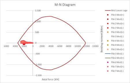
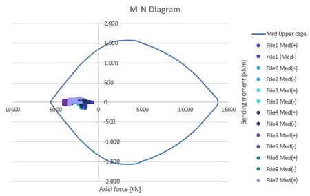
Figure 15: Structural verification on tension piles (Rabin Station).
Finally, with the same model, the global stability analyses have been performed. This was done by computing the factor of safety and checking the related failure surfaces (Figure 16).
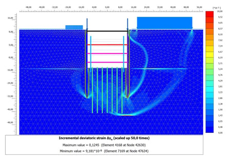
Figure 16: Example of global stability analysis and FS calculation.
Conclusion
The analyses presented as case studies in this article demonstrate the suitability of PLAXIS 2D FEM software for the geotechnical and structural design of the cut and cover excavations developed by Geodata Engineering, within the Green Line Metro in Tel Aviv.
PLAXIS has allowed the team to perform both geotechnical and structural designs. For example, the team could analyze ground settlements, clay swelling, and dewatering flow. At the same time, they could design reinforced concrete elements (i.e., diaphragm wall panels) and steel elements (i.e., struts and waler beams).