Rock engineering projects can be fascinating. Engineers working on rock need to design solutions that mobilize the natural strength of complex, largely unknown rock masses, which often play the roles of both loading and engineering material.
The Rock Your Analysis with PLAXIS series will discuss rock engineering applications, their challenges, and the resources that numerical modelers and geotechnical engineers can use to solve these problems by using PLAXIS geotechnical analysis software.
This first article will briefly introduce some of the topics in the series, which will be expanded upon in upcoming blog posts and webinars:
- Equivalent continuum and embedded discontinuities
- Softening and brittle behavior
- Time-dependent effects: Creep and swelling
- Support and reinforcement elements
Equivalent Continuum and Embedded Discontinuities
At some scale, all rock is fractured. Rock masses contain fractures of many sizes, which may include joints, bedding planes, schistosity planes, shear zones, and faults. These discontinuities naturally have an influence on the mechanical behavior of the rock mass, but their effect will vary depending on the relative scale of the discontinuities with respect to the dimensions of the mechanical problem. This is captured by the concept of ”representative volume element” (RVE), which leads to several modeling approaches:
- Continuum: When the scale of the discontinuities is significantly larger than the RVE, the rock matrix can be considered “intact” and represented as a homogeneous continuum with the characteristics of the rock material. Any discontinuities are deemed too large and too distant to the RVE to have a significant influence on its behavior.
- Discontinuum: When the discontinuities and the RVE are of comparable scale, interactions between individual blocks govern the mechanical behavior. The rock mass is represented as the combination of intact rock, considered as a homogeneous (equivalent) continuum, and explicitly modeled discontinuities with defined location, direction, and material parameters. These embedded discontinuities may either correspond to actual joints mapped from the site or representative joint sets generated statistically.
- Equivalent Continuum (a.k.a. the ”smeared approach”): When the scale of the discontinuities is significantly smaller than the RVE, their individual contributions tend to fade together. The resulting rock mass is homogenized into a pseudo-continuum, with material parameters corresponding to the combination of rock material and discontinuities, which are considered ubiquitous through the RVE.
In practice, continuum and equivalent continuum approaches are usually discussed together, with the ”equivalent” modifier often omitted, since the only difference between the two lies in the selection of material parameters, either to represent the rock mass or the intact rock material.
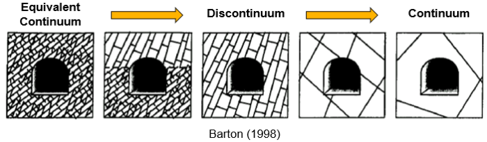
Image 1: After Barton (1998).
An overview of equivalent continuum constitutive models for rock was given in a previous series dedicated to soil and rock models. Those most prominent include:
- The classic Hoek-Brown (HB) model combines an elastic perfectly plastic stress-strain formulation with the generalized Hoek-Brown failure criterion for rock mass. Setting the Ground Strength Index, GSI = 100, and Disturbance factor, D = 0, reverts to the (original) Hoek-Brown failure criterion for intact rock, thus enabling the model to function both as a true continuum for intact rock and as an equivalent continuum for isotropic rock mass.
- The Jointed Rock (JR) model can represent the anisotropic behavior resulting from well-defined parallel joint sets. Up to three preferential directions can be defined, each subject to an independent Mohr-Coulomb failure criterion. The rock matrix is considered linear elastic, which means that plastic deformations can only occur along the predefined jointing directions.
In PLAXIS geotechnical analysis software, explicit discontinuities have traditionally been modelled through Interface elements. The new Discontinuity elements, introduced in Version 22 (2D only), enable a simpler modelling workflow. These are line (2D) or surface (3D) elements that decouple the nodes in the mesh, enabling the relative displacement between the two faces of the discontinuity, which are linked by a set of independent springs for which normal (kn) and shear (ks) stiffnesses can be specified. Finite element (FE) models with embedded discontinuities are still based on a continuum numerical framework and only enable small relative displacements. They cannot be used to model new contacts or the complete detachment of blocks.
Softening and Brittle Behavior
Working with brittle materials entails the risk of sudden failure. Most engineers are wisely told to avoid them in favor of ductile alternatives, but this is almost never an option in geotechnics. We must then find other ways to manage this risk.
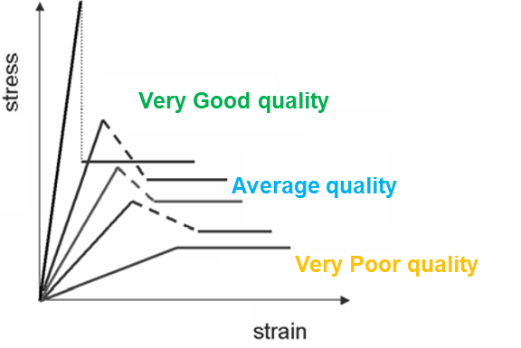
Image 2: After Hoek and Brown (1997) and Alejano et al. (2012).
A paradox in rock mechanics is that higher quality rocks are also more brittle. This partially negates the benefits of their higher strength. It also means that the conventional elastic-perfectly plastic approach underlying models like Mohr-Coulomb and the classic Hoek-Brown is only a good fit for lower-quality rock masses. While this approach is routinely applied to better quality rocks, large differences between peak and residual strengths generate difficulties for engineers:
- If residual strength is selected, the strength reserve around the peak will be neglected.
- If peak strength is selected, care must be taken to restrict strains well within the elastic range, avoiding the risk of going over the peak and triggering a sudden failure.
Both choices result in the under-utilization of the capacity of rock as an engineering material, which needs to be compensated with additional support and reinforcement measures. This limitation can be overcome if the actual softening/brittle behavior is considered, which is made possible by the new Hoek-Brown with Softening (HBS) model.
Varying the parameters that determine the shape of the post-peak branch, it is possible to go through varying degrees of strain-softening, from brittle failure (“critical softening”) to quasi-perfect plasticity. This can be applied according to two independent degradation regimes:
- Strength Softening Model (SSM): Direct degradation of the Hoek-Brown parameters (mb and s).
- GSI Softening Model (GSM): Indirect degradation through decreasing the GSI.
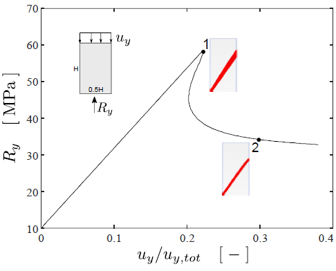
Image 3: Marinelli et al. (2019).
Modeling materials that undergo strain softening is always a challenge in the FE method. Softening failure develops through shear bands. These are highly localized plastic zones where deformations rapidly concentrate while the rest of the medium remains undisturbed, even unloading. Without further treatment, these heterogeneous deformations would lead to mesh-dependent numerical solutions, which are obviously not a good representation of the physical (mesh-free) reality. To restore the objectivity of the solution, a viscous regularization procedure based on Perzyna (1966) is applied. This makes the HBS model more stable and faster to converge than the classic HB model for highly non-associative problems (those where the dilatancy angle, y, is much lower than the equivalent internal friction angle, feq, defined by the Hoek-Brown failure envelope).
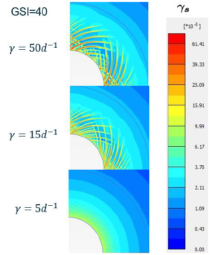
Image 4: Zalamea et al. (2020).
Time-dependent Effects: Creep
Creep can be defined as the viscous deformation of solids under stresses below their yield point. Creep develops in time and its speed is dependent on the temperature. As they approach their melting point, all rocks become viscous. Some, like argillite or rock salt, exhibit creep even at relatively low temperatures.
Creep can induce additional forces in the support and reinforcement elements, together with a changing distribution of stresses.
The Norton-based Double Power Creep (N2PC) model has recently been upgraded. It can now be used in two modes: either the previous visco-elastic formulation to model only the long-term effects of creep, or the new visco-elasto-plastic model with a Mohr-Coulomb failure surface, which also enables the consideration of the short-term effects. Additionally, in PLAXIS 2D, the N2PC model can also consider the dependency of creep from temperature.
Time-dependent Effects: Swelling
Rocks containing clay minerals (like claystones, shales, or marls) or anhydrite are susceptible to swelling in the presence of water. Swelling is due to chemo-mechanical processes:
- Clay minerals trap water mostly by osmosis, due to differences in cation concentration in the rock matrix and the free water. Swelling of clays is proportional to the content of sheet silicates and montmorillonite minerals in the rock matrix.
- Anhydrite (CaSO4) forms gypsum crystals (CaSO4H2O) when it hydrates, which may result in a volume increase of up to 60%. As gypsum is easily solvable in water, it can travel large distances before precipitating. This may cause gypsum growth and swelling to occur far from the anhydritic rock where it originates.
Swelling typically shows as heave at the bottom of the excavation or, in closed cross sections, lifting of the whole tunnel, but it can also result in collapse. Like most engineering challenges, it is much more cost-effective to prevent swelling during design than to mitigate once it appears. Designing for swelling rock commonly requires additional support, especially at the invert, yielding elements to accommodate the expected deformation, or downwards anchors to resist uplift. Repairing it on an existing tunnel often demands a full reconstruction of the swelling sections.
The Swelling Rock model can account for the presence or absence of water: only wet rock masses will develop swelling deformation.
Support and Reinforcement Elements
According to Windsor and Thompson (1993):
- Reinforcement is a means of conserving or improving the overall rock mass properties from within the rock mass by techniques such as rock bolts, cable bolts, and ground anchors.
- Support is the application of a reactive force to the surface of an excavation, including techniques such as timber, shotcrete, steel mesh, or reinforced concrete lining.
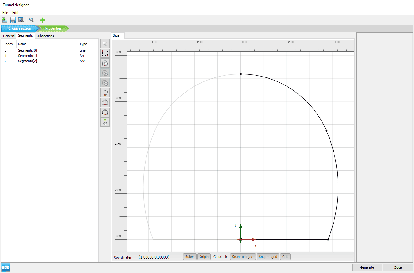
Support and reinforcement elements can be modeled with components from the equivalent continuum constitutive models for rock. In underground construction, the Tunnel Designer also enables the quick parametric definition of patterns and construction sequence.
Reinforcement elements take the shape of 1-dimensional cables, bars, or poles. Although there is a wide variety of commercially available elements with different coupling systems, they all can be represented analytically either as point-to-point connection (unbonded length), a segment interacting with the surrounding rock (bonded length), or a combination of both. In PLAXIS, unbonded segments can be represented with node-to-node anchors and bonded segments with embedded beams.
Support elements typically take the shape of 2-dimensional shells or membranes, and occasionally of volumetric elements. In PLAXIS, rigid shells can be modeled with plate elements and flexible meshes with geogrid elements. Volumetric elements can either be modeled directly or through the thick lining feature in the Tunnel Designer.
References
Alejano, L.R., Alonso, E., Rodríguez-Dono, A., Fernández-Manín, G. (2010). Application of the convergence-confinement method to tunnels in rock masses exhibiting Hoek–Brown strain-softening behaviour. International Journal of Rock Mechanics and Mining Sciences, Volume 47, Issue 1, p. 150-160,
Barton, N. (1998). Quantitative description of rock masses for the design of NMT reinforcement. Int. Conf. on Hydro Power Development in Himalayas. Shimla, India.
Hoek, E. and Brown, T. (1997). Practical estimates of rock mass strength. International Journal of Rock Mechanics and Mining Sciences, Volume 34, Issue 8, p. 1165-1186.
Marinelli, F., Zalamea, N., Vilhar, G., Brasile, S., Cammarata, G., Brinkgreve, R.B.J. (2019). Modelling of brittle failure based on Hoek & Brown yield criterion: parametric studies and constitutive validation. In Proceedings of 53rd US Rock Mechanics/Geomechanics Symposium, New York, 23-26 June 2019. Paper 19-410.
Perzyna, P. (1966). Fundamental problems in viscoplasticity. Advances in Applied Mechanics, 9:243-377.
Windsor, C.R. and Thompson, A.G. (1993). Rock reinforcement – technology, testing, design and evaluation. Comprehensive Rock Engineering, 4: 451–84. Pergamon: Oxford.
Zalamea, N., Marinelli, F., Cammarata, G., Brinkgreve, R.B.J., Brasile, S. (2020). Numerical analyses of shear bands failure in tunnel excavation problems using a regularized Hoek-Brown model. In Proceedings of 54th US Rock Mechanics/Geomechanics Symposium, Golden, Colorado, 28 June-1 July 2020. Paper 20-1797.
Learn more about how to save money on your geotechnical projects by using PLAXIS