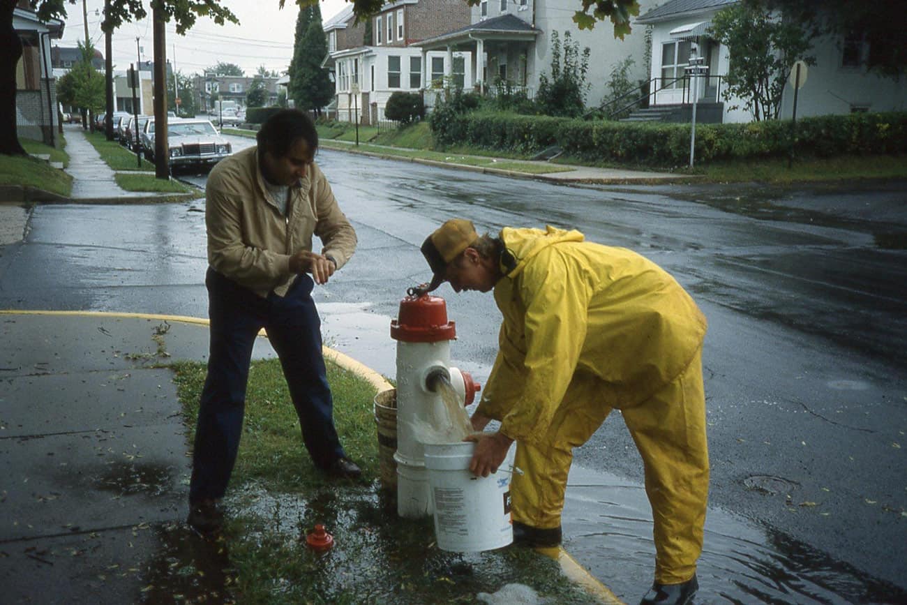

Pretty much everyone who has worked in water distribution has been involved with hydrant flow testing at one time or another. It’s not very difficult. Place a pressure gauge on a residual hydrant and flow a nearby hydrant while recording the hydrant flow and the pressure at the residual hydrant with no flow and with flow. The procedure is documented in many places (AWWA, 2016).
Results are usually plugged into the formula below to determine the available fire flow as some residual pressure (usually 20 psi in North America).
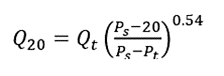
Where Q20 = flow at 20 psi, Qt = flow during hydrant flow test, Ps = pressure during static condition, Pt pressure during hydrant flow test.
The primary purpose of these tests is to evaluate the capacity of the distribution system, especially during fires. It is a key component that the Insurance Service Office (ISO) uses in determining the Public Protection Class (ISO, 2012) that combines that result with other factors like the quality of the fire department.
A secondary purpose is in calibrating water distribution system models. Calibrating a model only for normal day demands does not give much indication of whether the model is accurate when used for an emergency situation, as when velocities increase in a fire.
The downside of a hydrant flow test is that it requires two people to run it. I’m frequently asked, “Why can’t I just put a pressure gauge on one of the other hydrant outlets and measure the residual pressure and hydrant flow at the same hydrant?”
To answer that question, it’s important to first understand that a hydrant flow test is conducted to understand the strength of the distribution system, not of the hydrant. Those using the test want to understand how strong the distribution system is. Ideally, residual pressure should be measured at the point where the hydrant lateral is tied into the water main, but utilities are not going to excavate the pipe and install a pressure tap just to evaluate the system. So, the nearest hydrant in the pressure zone is used as the residual hydrant.
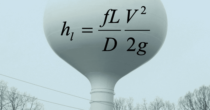
For example, if you measure the residual pressure correctly at a nearby hydrant, you may get a value like 45 psi. If you took a pressure reading at the flowed hydrant at the same time, you would get a value around 30 psi. Why is the lower value incorrect? It is obscured by the head loss in the hydrant lateral and barrel and the conversion of pressure head to velocity head at the outlet. The value determined by the Q20 equation above would be much lower than the correct value.
In terms of model calibration, if you used the value from the flowed hydrant, you would actually be calibrating the hydrant lateral rather than the distribution system model.
So, there really is no such thing as a one-hydrant flow test. The pressure you would measure with the static pressure gauge on the flowed hydrant would be very close to the value of the pressure gauge on the hydrant pitot.
Why then would you open a hydrant and simply measure the flow and pressure? One case is you are interested in knowing how much water you could put on a fire if the grass right in front of the flowed hydrant is burning. Not a common use case. The second reason is that you are planning flushing and you’d like to know how much water you will get when you open a hydrant. First, you can use your model to determine the flushing flow. Second, you can measure that flow the first time you do any flushing and if you record it, you’ll have that value on file the next time you plan to flush. However, that value will only be correct for the isolation valve status at the time you measure the flow. If you close any valves to conduct uni-directional flushing, the flow will decrease. Finally, if you are going to be flowing hydrants, you should have at lease two people out there anyway, just for safety reasons.
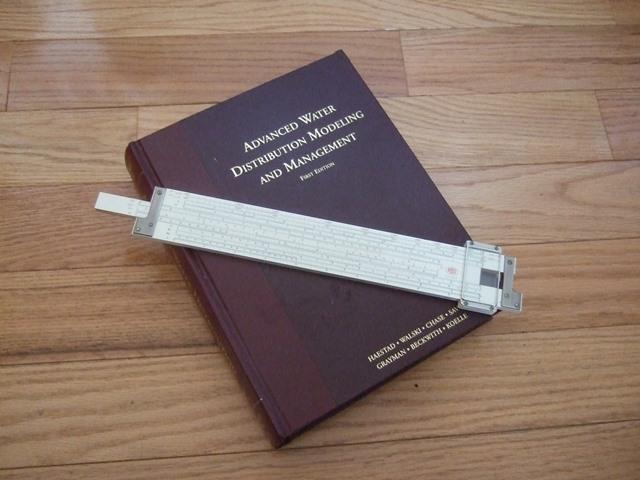
If you want to see the math behind the equations used, you can go to Bentley’s Advanced Water Distribution Modeling and Management book, pages 451-453.
References:
AWWA, 2016, Installation, Field Testing and Maintenance of Fire Hydrants, AWWA Manual M17, Denver, CO, https://engage.awwa.org/PersonifyEbusiness/Store/Product-Details/productId/59340080
Insurance Services Office, 2012, Fire Suppression Rating Schedule, Insurance Services Office (a subsidiary of Verisk), Atlanta, GA, https://www.isomitigation.com/ppc/fsrs/
Walski, T. et al., 2003, Advanced Water Distribution Modeling and Management, Bentley Systems, Exton, PA, https://www.amazon.com/Advanced-Water-Distribution-Modeling-Management/dp/1934493015