Pretty much all well-run water utilities periodically develop a master plan. The plan looks out 20, 30, 40 years and tries to layout development in source, treatment, and distribution systems. Based on the best available demand forecast, pipes, tanks, and pumps are laid out to evolve the system efficiently.
Some people think that planning the size of future pipes is the most important decision in the master plan. But pipe size decisions can be modified. Suppose the plan is to install a 30 in. transmission main in 2030. However, if demand increases are running ahead of the projection, there is still time to upsize the pipe to 36 in. or accelerate the installation to 2028.
I maintain that the most important decision is the overflow elevation of the tank in a new pressure zone. Once the overflow elevation of the tank is set, the pressure zones and the area covered by the pressure zone are also set. From there, the location of the storage tank can be identified, and the path from the treatment/pumping facility can be determined.
Let’s take a look at an example. Suppose you set the tank overflow to 250 ft with a normal low level of 230 ft and a ground elevation of 210 ft and that you want normal day pressure to be between 80 and 35 psi. In terms of elevation, who can expect to get good service from the pressure zone controlled by the tank?
Highest customer = 230 – 35 * 2.31 = 150 ft
Any customer above this elevation will not routinely get 35 psi. Yes, we can discuss whether 35, 30, 25is the correct value, but that’s subject for another blog, and the number may be controlled by regulation.)
Lowest customer = 250 – 80 * 2.31 = 65 ft
Anyone below this elevation can receive excess pressure.
This is illustrated in the figure below.
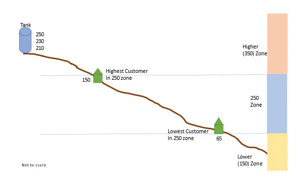
Customers at elevations between 65 and 150 ft will have good pressure. Customers outside this range will need to find another pressure zone.
The engineer doing the planning needs to check where the growth is expected. If it will extend up to 170 ft but no higher, it may be better to raise the tank elevation to 270 ft.
The size step between pressure zone hydraulic grades should be on the order of 100 ft. Too small of a step will result in a tiny, inefficient zone, while too large of a step will result in some customers getting pressures too high or too low.
Once the elevations are set, they should be immortalized in a contour map. In one place I worked decades ago, we took USGS topo maps and shaded them in using pastel-colored pencils with a different color for each zone and the colors extending well beyond the extent of the existing system into areas that would be developed in the future (remember, it’s planning). Nowadays, you can highlight these contours in your model or your GIS and shade between the contours digitally.
Suppose you haven’t developed these boundary contours. Some developer will want to place their development across a pressure zone boundary and will not be happy when you tell them they need to pay for a pump station because they want to serve houses above the high contour for the zone. This is illustrated below.
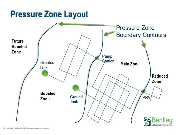
A developer near the ground tank may want to get service from the ground tank, but they may be at an elevation that needs to get water from the boosted zone served from the elevated tank.
As the culmination of the master plan, you’ll want to prepare a system profile like the one below.
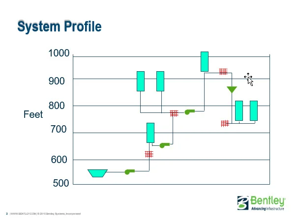
These profiles can get pretty complicated. We once put one together that included 104 pressure zone, and it’s complicated.
But there are exceptions in systems where the tank water level doesn’t float on the system. For example,
- Zone with no tank. The pump controls the hydraulic grade, but the pump should be selected to run at a hydraulic grade that may be installed in the future consistent with the master plan. That’s why it’s called the master plan. If the elevation of the development is at 110 ft in our example above, the pump discharge should be set to a hydraulic grade of 250 ft.
- Zone may have pumped storage tank. See number 1 above, plus last week’s blog.
- Zone with a hydro pneumatic tank. Again, the hydraulic grade should be consistent with the hydraulic grade for those elevations because one day, everything will be connected, and the hydro pneumatic tank will be no longer needed.
But Tom, when can I run the model? I want to run OpenFlows WaterGEMS. The material above relates to a new distribution system, an extension to an existing system into a new area, or an isolated system that will one day be merged in with the main system. The selection of overflow elevations and hence pressure zone boundaries is step zero in the distribution planning process and is done before the modeling of that area begins. Once the tank overflow is set, the engineer can have all sorts of fun running the model to sizing pipes, selecting pumps, determining the volume of tanks, placing control valves, and deciding when to install various components.
Want to learn more from our resident water and wastewater expert? Join the Dr. Tom Walski Newsletter today!