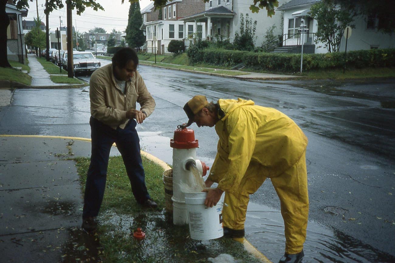

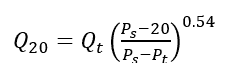
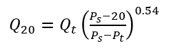
Those of you who work with water distribution systems generally need to determine the flow that can be delivered to a fire at some minimum residual pressure, which in the US is 20 psi in most jurisdictions. In most cases, this is determined by conducting a fire hydrant flow test which measures the pressure at a residual hydrant while flowing a nearby test hydrant. The flow at 20 psi (called Q20 or distribution system capacity) is then calculated using this equation.
 (1)
(1)
Where Q20 = flow at 20 psi residual, Qt = flow during test, Ps = static pressure, Pt = pressure during test
Pressures are measured at residual hydrant, not the flowed hydrant.
But where did this equation come from and what assumptions are contained in it? The equation comes from the Insurance Services Office (ISO) and it was most likely developed by its predecessor the National Board of Fire Underwriters. I can’t find the original paper, so I went back and re-derived it myself to understand what it’s made of.
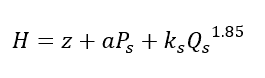
Write out the energy equation for three cases:
Static
 (2a)
(2a)
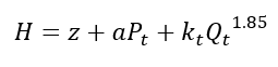
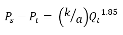
Test flow
 (2b)
(2b)
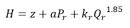
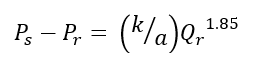
Residual condition
(2c)
Where H = hydraulic grade for zone, z = elevation of residual gage, a = conversion factor for head to pressure units (e.g. 2.31), Qr = flow at residual pressure r, k = coefficient to calculate the effective head loss from source to residual hydrant for each case.
Some assumptions so far include
- The head in the zone source is the same across all three cases (e.g. tank level, pump discharge, PRV outlet). Some of these boundary conditions may not be constant.
- The k values don’t change between the cases. This means that the distribution system is represented by and equivalent pipe and won’t be true if the flow paths significantly change.
- The flow across the zone in the static case causes negligible head loss compared with the head loss during the other cases (Qs ~ 0) and therefore H – z = Ps for all cases.
- The residual and flowed hydrants are sufficiently close to one another that you don’t need to worry about the distance between them. This means that the pressure at the residual gage is roughly the same as the pressure at the tap for the flowed hydrant.
- It doesn’t matter how many hydrants that are opened to achieve the flow.
Substitute H – z for Ps and rearrange.
 (3a)
(3a)
 (3b)
(3b)
Divide equation (3b) into (3a), raise each side to the 0.54 power, cancel out k and a, and set Pr = 20 psi, and you get equation (1).
You can see that there are a lot of assumptions that are built into the ISO formula. They aren’t too bad for the overwhelming majority of cases. But there are some situations where a hydraulic model run can be more accurate.
The assumption that has the most impact on results is that the static hydraulic grade is the same across all three cases. Suppose the test is conducted in a system close to a PRV feeding the zone from a higher zone but this PRV is normally closed. If during the flow test, the pressure is not dropped sufficiently to make the PRV open, then the flow at the residual case will underestimate the fire flow because the k values would not be constant.
On the other hand, suppose that the pump feeding this zone is only sized for normal demands. During the fire, the pump will run out on its curve and cause the source head to drop. The equation can’t account for that.
A more accurate and robust way to determine the flow to the area is to use your hydraulic model to calculate the distribution system capacity. This is done automatically in WaterGEMS/WaterCAD fire flow analysis. If you want to do it manually, simply replace the residual hydrant by a fixed node which will cause the pressure to be 20 psi (e.g. a reservoir node with water level 46 ft above the ground). The flow into that fixed grade node would be the flow that can be delivered at that residual pressure.
But what about the availability of hydrants to deliver the water? That is an entirely separate calculation. For example, at the intersection of two 48 inch pipes, the main capacity (Q20) is a huge value. But if there is only a single hydrant nearby, the available fire flow will only be 1500 gpm according to rules used by ISO for evaluating available fire flow
The available fire flow is the lesser of supply capacity, hydrant distribution and main capacity. Main capacity is usually the limiting factor and is often equated with available fire flow.
This process may sound imprecise, but that is the nature of estimating needed and available fire flow. Needed fire flow is usually rounded off to the 250 gpm. Fire engineers are not so much concerned about whether the flow is 1000 gpm vs. 1015 gpm but is the flow 1000 gpm vs. 1250 gpm.
Overall, the hydrant test equation is useful and has survived the test of time. However, it is helpful to understand the assumptions that are involved with it and the value of a hydraulic model when those assumptions become questionable.