
One of the most common questions we get from our WaterGEMS/WaterCAD users is how to model the connection between a proposed land development and the water distribution system supplying it. The engineer wants to be able to model the piping to design the development, but doesn’t know how to account for the flow available from the supply system.
The engineer sizing the pipes in the development has a model of the internal piping, but needs to know how to describe the supply system. This is one of those cases where there is a “right” way to model the situation and a number of shortcut solutions that may work if the underlying assumptions are met.
The Problem
The engineer would like to specify a hydraulic grade (HGL) or a known inflow from the supply system. However, neither of these values are a constant, and they depend on the supply system and the amount of water being drawn by the development. The right way, in my opinion, is to model the supply system (or at least the immediate pressure zone) back to the source, whether it is a treatment plant or well or a tank with relatively constant HGL. A fairly skeletonized model will work in this case.
The problem is that the engineer doesn’t want to mess with a model of the supply system, even if the supply system is willing to share the model with the engineer, which isn’t always the case. In some other cases, the engineers for the supply system may provide model results to the developer’s engineer (more on this later), but this tends to be the exception. In some other cases, the developer’s engineer may build a highly skeletonized model of the supply system, but the data is not always available, and the developer does not want to pay the engineer to model the supply system.
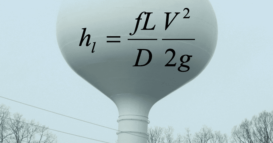
Theoretically, the difficulty lies in determining the head loss between the source and the connection point. This determines the HGL, and as mentioned above, it varies depending on a number of factors.
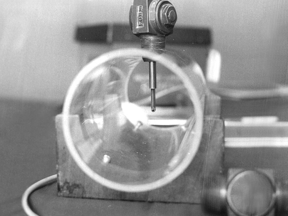
One type of data that is very useful for these analyses is a fire hydrant flow test as near the connection point as possible. This will show up in several cases below.
Alternative Approaches
There are options depending on the situation. Let’s review them and the pros and cons.
All-pipes model. A calibrated all-pipes model of the supply system and development is the best solution. With such a model, it is possible to simulate all sorts of conditions such as peak days, fire flows, minimum nighttime flow, and others to see how the system will behave. Some water suppliers will actually run the model with a description of the layout and demands in the development, but these are the exception.
Fixed HGL at connection point. The easiest way to model a connection is by setting an HGL (pressure) at the connection. This can sometimes work when the HGL is indeed constant. This might be the case when the supply system has a tank near the connection point where the HGL never drops below, say 850 ft, and the supply system pipe has virtually no head loss from the tank to the connection (say it’s a 24 in. supply to a 6 in. tap to the development). A reservoir element can be used to model the supply HGL. This is seldom the case, as the HGL at the connection will vary, and much of that variation may due to withdrawal from the development. One way to check on this is to install a pressure logger at the connection point and observe how the HGL varies, especially during peak demand periods. But this only captures HGL variations on normal days. In many cases, the fire flows are much higher than normal demand, and the best way to understand the variations is to conduct a hydrant flow test near the connection. This will show the variation in HGL over a range of conditions.
Another approach using a fixed HGL is to use a worst-case value for HGL at the connection. This may correspond to a pressure of 20 psi or 35 psi, or some other value at the connection. Regardless of what changes are made in the supply system, the system will supply this pressure. This, however, tends to lead to very conservative designs.
In some cases, even though the supply system is reluctant to provide their hydraulic model to the developer, the modelers for the supply system may be willing to make model runs for various scenarios to calculate pressures at the connection point for different conditions or planned changes to the system.
This can also work in the case where the “Land development” is trivial. An example might be a strip mall with a mini-mart, a dry cleaner, a pizza restaurant, and a manicure shop. But it won’t work where the impacts of the development become significant.
Known Inflow to Development. It may be tempting to simply specify a known inflow to the development using a negative demand at the connection point. This doesn’t work well for demand-driven models. Say the inflow to the project is set to 300 gpm, but the demand is 180 gpm. The solver doesn’t like this because 300 = 180 is not a valid equation. Error messages will be common unless there is elevated storage in the development or at least pressure-dependent demand. In addition, this approach assumes the supply system can actually supply a constant 300 gpm at the required pressure.
An approximation is to set a hydraulic grade at some fixed realistic value and use a flow control valve (FCV) to restrict the flow to a value that actually can be delivered. This can be accurate in those cases where the supply system agrees to provide some fixed maximum flow, say 1200 gpm, and they have installed a real FCV to limit that flow. There may be some legal agreement as to maximum supply. Such valving setups are rare.
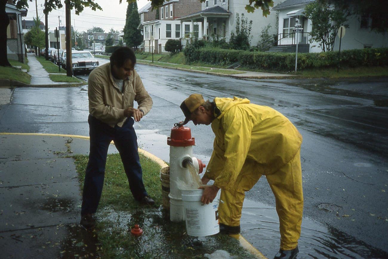
Simulation using Reservoir and Pump. The problem with the above approaches is that it is difficult to understand the effect of head loss in the supply system over a range of conditions. This is where a hydrant flow test can be very useful. With a standard two-hydrant flow test, it is possible to know the HGL at the connection point (actually the residual hydrant) both during normal demand (static condition) and high flow condition (hydrant flow). The approach involves setting a reservoir node at the elevation of the residual pressure gauge and placing an equivalent pump between that node and the connection. The shape of the pump curve approximates the shape of the flow vs. HGL at the connection.
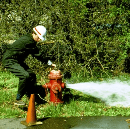
Figure 1: A hydrant flow test provides useful data to understand the source system
The steps to set up this type of connections and the limitations are described here in our Wiki.
Communications
An important aspect of designing the piping in a new development is for the developer’s engineer to talk with the supply system hydraulic engineers. The supply system engineer can confirm if the connection is being made at the best location. The developer’s engineer may want to connect to a 6-inch pipe when there is a 16-inch pipe right around the corner that may be a much better source.
In addition, today’s system may be undergoing changes. The supply system may be adjusting pressure zone boundaries that will dramatically modify connection pressures. Or they may be installing a new transmission main or elevated tank that can greatly change system capacity.
It is also important that the supply system does not guarantee that certain pressures and flows can be delivered. Systems can change for a variety of reasons, such as new construction, pressure zone boundary changes, demand growth, pipe breaks, and pump and valve operations. Data provided by the supply system reflected the system condition when the data were collected, and model results reflect conditions that were simulated in that run. They are not a guarantee of future flows and pressures. Conditions can change.
Summary
With all the assumptions and uncertainties in modeling connections to existing systems, the model remains a valuable tool for hydraulic design. It enables the engineer to quickly consider a wide variety of situations to develop the best possible design. Provision of adequate fire flows are often the driving factor in pipe sizing for most land development projects. Tools like Bentley’s OpenFlows fire flow analysis can greatly facilitate pipe sizing by pointing out where fire flow flows are inadequate and modify piping to meet needed fire flow.
Connections to new land development projects are a very common use case for WaterGEMS and WaterCAD users. With these products, engineers have a great set of tools for doing a solid hydraulic design in spite of the hurdles.