Rock at depth is subjected to stresses resulting from the weight of the overlying strata and from locked-in stresses of tectonic origin. When an opening is excavated in this rock, the stress field is locally disrupted and a new set of stresses are induced in the rock surrounding the opening. A knowledge of the magnitudes and directions of these in situ and induced stresses is an essential component of underground excavation design since, in many cases, the strength of the rock is exceeded and the resulting instability can have serious consequences on the behavior of the excavations.
PLAXIS provides many specific modeling features for deep underground excavation in rock mass that this article will briefly cover.
Initial Stress Conditions
In general, estimating in situ stresses requires a detailed characterization of the site geology and considerable judgement. The state of stress that exists in a rock mass today is a function of its geological history, rock mass properties, and the boundary conditions that are currently being applied. Knowing this, it is apparent that predicting a stress state in a rock mass today is not practical given the complex geological history that ancient rocks have endured.
Still, it is common practice to make two basic assumptions when estimating the state of stress at any depth, z, in a rock mass:
- The first assumption is that the state of stress can be described by two components: a vertical component, σv, due to the weight of the overlying rock at that depth and equal to y.z (where y is the average unit weight of the rock in N/m3), and a uniform horizontal component, σh =K. σv
- The second assumption is that both σv and σh are principal stresses. In general, σv and σh are taken as total stresses for rock masses.
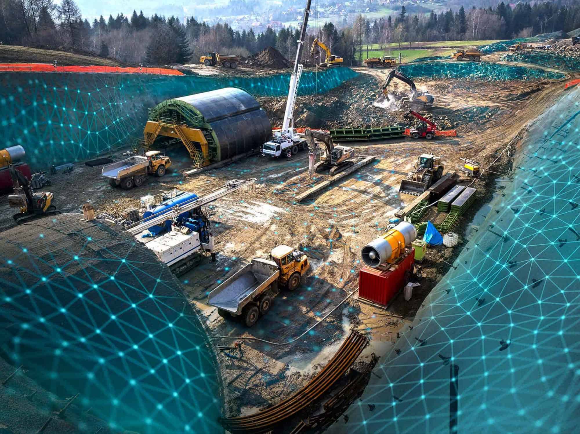
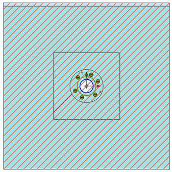
This strategy can easily be used in PLAXIS for the definition of initial stress, called the K0-procedure. When in situ stresses can be measured and both intensity and orientation of the principal initial stresses can be experimentally assessed, the field stress procedure can be used. Then it is possible to initially create a uniform state of anisotropic stresses with user-defined stress directions and amplitudes (see Figure 1).
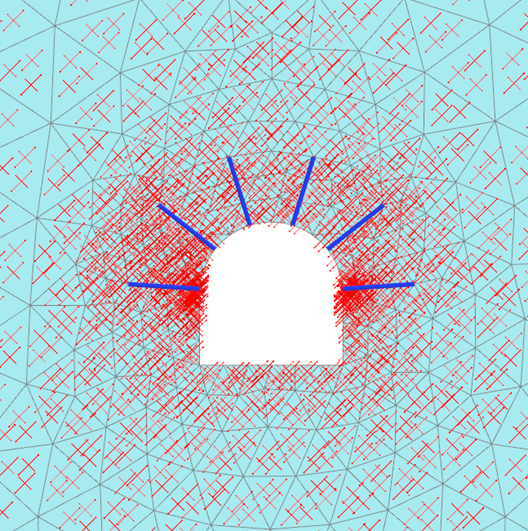 Figure 1: Rock mass initial stresses generated in PLAXIS using the field stress procedure.
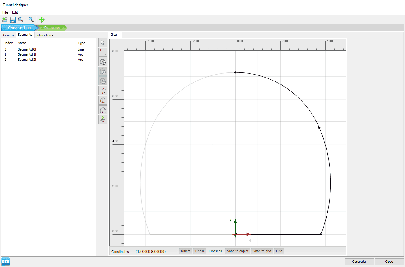
Tunnel Designer
PLAXIS provides a specific functionality for the modeling of tunnels. It contains sets of features for easy geometry definition of the theoretical excavation spaces and sub-spaces, tunnel lining and shotcreting, rock bolts, trajectory, and excavation routines for fast construction stage definition and regeneration (see Figure 2).
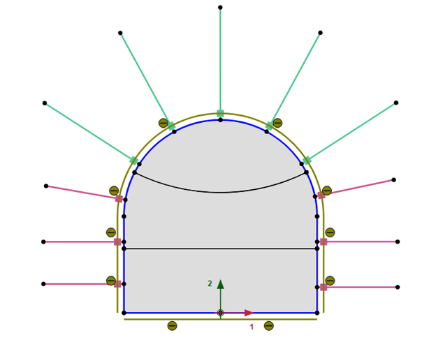 (a) 2D sketch in PLAXIS Tunnel Designer
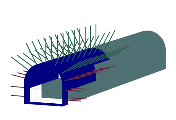 (b) 3D model representation
Figure 2: Tunnel model generation using the Tunnel Designer feature in PLAXIS.
Rock Discontinuities
Rock masses can be characterized by the existence of discontinuities. “Discontinuity” is a general term denoting any separation in a rock mass having zero or low tensile strength. It is the collective term for most types of joints, weak bedding planes, weak “schistocity” planes, weakness zones, shear zones, and faults. Discontinuous rock masses are usually weaker, more deformable, and highly anisotropic when compared with intact rocks. Specific discontinuity elements are available in PLAXIS for the consideration of discontinuous rock mass. These discontinuity elements are line elements in 2D and surface elements in 3D that allow the user to define the shear strength accordingly to Mohr-Coulomb criterion only and to input the values of normal and shear stiffnesses with respect to the discontinuity line.
 (a) Discontinuity elements definition in PLAXIS 2D Input.
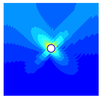
(b) Displacement contour plots in Output
Figure 3: The use of PLAXIS discontinuity elements for modeling rock joints.
Rock Reinforcement
Rock reinforcement is used to improve the strength and/or deformational behavior of the rock mass. The reinforcement generally consists of bolts or cables that are placed in the rock mass in such a way that they provide confinement or restraint to counteract loosening and movement of the rock blocks. They may or may not be tensioned, depending upon the sequence of installation, and they may or may not be grouted, depending on whether they are temporary or permanent. PLAXIS provides a specific element for such a purpose: the so-called embedded beam elements. They introduce the appropriate stiffness corresponding to the reinforcement element to the finite element model through a beam element (material stiffness along with cross section shape and dimensions). The beam element is then connected to the surrounding rock mass by means of coupling springs with elasto-plastic behavior. The value of shear force developing in the coupling springs is calculated proportionally to the relative displacement between the reinforcement and the rock mass but being limited by a maximum traction value Tmax defined by the user along the reinforcement length. Such elements are perfectly suited for the modeling of rock bolts as shown in Figure 4.
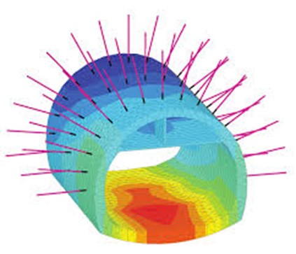 Figure 4: Rock bolt in PLAXIS 3D
Creep Effects
The excavation of underground openings in rock relieves the “in-situ state” of stresses, providing an initiating mechanism for time-dependent deformation in rocks to occur. The construction of a permanent lining restrains the rock movement, resulting in an increase with time of pressure acting on the lining which needs to be properly assessed during structural design. PLAXIS provides both linear and non-linear creep models (Kelvin chain, Norton creep models), enabling the calculation of the evolution of both the convergence and the lining structural forces following the excavation of a tunnel in rock mass.
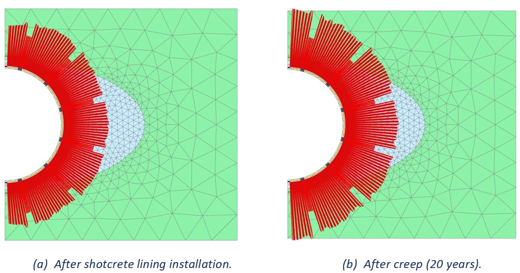 Figure 5: Evolution of normal forces in shotcrete lining.