The accurate, long-term deflection calculation of concrete floors is a difficult task. It requires rigorous consideration of cracking, tension stiffening, and associated long-term effects such as creep and shrinkage. While most concrete designers understand how externally applied floor loads and creep can contribute to cracking, they often incorrectly calculate or even ignore restraint to in-plane shrinkage and/or thermal strains as a source of cracking. This can have severe consequences, including costly serviceability issues that are only noticed long after building construction is completed.
This article focuses on restraint cracking and long-term deflection calculation. The article will attempt to:
- Distinguish between two sources of restraint – internal and external
- Discuss a common method for including shrinkage restraint effects in a finite element analysis
- Describe RAM Concept’s method for accounting for shrinkage restraint effects
Although the concepts discussed in the article apply to both shrinkage and thermal effects, restraint effects will be referred to as “shrinkage” restraint for the remainder of the article.
Sources of Restraint
The sources of shrinkage restraint can be broadly classified into two groups: internal restraint and external restraint.
Internal shrinkage restraint is associated with sources within the concrete floor surfaces. For a typical concrete design section, the bonded reinforcement is the primary source of internal shrinkage restraint. As concrete shrinks, the reinforcement is compressed, and an equal and opposite tension force is induced in the concrete. When the reinforcement in the section is asymmetric (more bottom reinforcement than top reinforcement, or vice versa), there is a higher level of restraint on one face of the section and a curvature is imposed on the section. This curvature adds to the curvature associated with externally applied loads when more reinforcement is placed on the tension face of the flexural section. In extreme cases, such as a section with excessive reinforcement on a single face, the internal shrinkage restraint effect may crack the floor in the absence of superimposed loads.
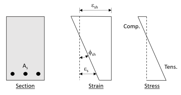 Figure 1 – Internal Shrinkage Restraint Curvature in Uncracked Section
External shrinkage restraint is associated with sources outside the concrete floor surfaces. In general, stiff walls restricting in-plane displacement of the floor are the primary source of external restraint. However, column supports can contribute to external shrinkage restraint, especially at the lowest level when they are attached to stiff foundations. Concrete floors subject to shrinkage tend to displace toward the center of rigidity of the floor. When supports restrict that shrinkage movement, tension stress is induced in the concrete. The external shrinkage restraint effect increases as the support stiffness increases and as the eccentricity of the support from the center of rigidity increases. As with the internal shrinkage restraint effect, external shrinkage restraint can cause cracking in highly restrained floors in the absence of applied loads.
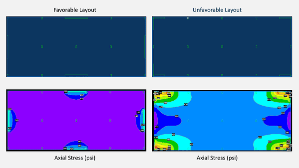
Figure 2 –Favorable versus Unfavorable Wall Layout
Common Design Methods
Shrinkage restraint is difficult to capture analytically because a complex, non-linear solution is required. To simplify the calculations, many engineers rely on approximate methods to account for shrinkage restraint cracking. The most common method is to use a reduced concrete modulus of rupture or cracking moment in the analysis so that cracking is detected at a lower stress threshold. Two frequently used effective modulus of ruptures used with the ACI design code are 4*sqrt(f’c), which is referenced in ACI 435R-95 “Control of Deflection in Concrete Structures,” and 5*sqrt(f’c), which corresponds to 2/3 of the cracking stress and aligns with the tension stiffening equation in ACI 318-19 24.2.3.5.
While the reduced modulus of rupture method is easy to apply in practice, it has some disadvantages:
- The method implies that restraint cracking is a function of the applied loading. However, as noted above, shrinkage restraint cracking can occur in highly restrained floors in the absence of externally applied loads. It would not be appropriate to reduce the modulus of rupture to 0 to capture the cracking behavior for such a case.
- The method is not directly associated with a degree of restraint, which varies with reinforcement ratios and wall stiffness/location. For highly restrained floors, modulus of rupture values less than 4*sqrt(f’c) or 5*sqrt(f’c) might be more appropriate, but the determining the appropriate value is left to engineering judgement.
- The method uses a single reduction to combine two separate effects. However, internal shrinkage restraint and external shrinkage restraint are different behaviors. Combining their effects with an approximate reduction can cause confusion. For example, some engineers argue that the method is intended to account for both sources of restraint, while others use it to account for only internal shrinkage restraint.
RAM Concept’s Method
RAM Concept’s load history analysis calculates long-term deflections using detailed cross section calculations that account for both internal and external shrinkage restraint, as well as other critical behaviors like load sequence, early age concrete strength, material non-linearity, tension stiffening, and time-dependent effects.
RAM Concept rigorously accounts for the internal shrinkage restraint effect at each design cross section using detailed strain/curvature calculations, which consider all reinforcement intersecting the section and time-dependent shrinkage strains for each step in the load history. The approach is similar to the calculation outlined in Eurocode 2-2004 Clause 7.4.3(6) Equation 7.21.
RAM Concept accounts for external shrinkage restraint separate from internal shrinkage restraint using an input External Shrinkage Restraint setting (none, mild, moderate, or severe), which is mapped to a restraint percentage, or a custom percentage directly input by the user. For each load stage, the restraint percentage is multiped by the shrinkage strain to determine an estimated shrinkage strain associated with the external shrinkage restraint effect. That strain is then combined with the strains caused by applied loads and other effects and used to calculate a stress used in the cracking calculations.
RAM Concept’s method offers the following advantages:
- It associates both internal shrinkage restraint and external shrinkage restraint effects with the actual shrinkage behavior instead of indirectly through a cracking stress reduction. This means that RAM Concept can easily detect cracking in highly restrained floors, even if it occurs in the absence of an externally applied load.
- It calculates the internal shrinkage restraint at each cross section using the specific reinforcement ratio at those sections. This means that RAM Concept can account for varying levels of internal shrinkage restraint in different areas of a floor.
- It processes the internal and external shrinkage restraint effects separately. This means that RAM Concept users can ignore external shrinkage restraint without affecting the internal shrinkage restraint calculations or study its importance using a range of values.
RAM Concept also summarizes important calculated parameters in tables and plots to help engineers quickly verify unexpected results and isolate the effects of the different behaviors (creep, shrinkage, cracking, etc.). Using this information, engineers can determine the relative importance of internal shrinkage restraint or external shrinkage restraint to the load history deflections. They can also identify areas where cracking is expected using contour plots that map the ratio of axial stress to cracking stress across the floor.
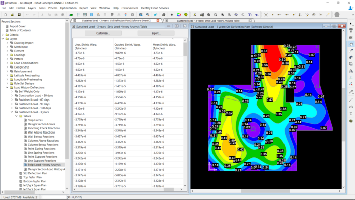
Figure 3 –Reviewing Load History Deflections and Internal Shrinkage Restraint Curvatures
Load History Deflection Analysis in Action
Concrete designers rely on RAM Concept’s load history deflection analysis to control long-term deflection, especially for aggressive designs consisting of thin slabs and/or limited reinforcement.
Baldridge & Associates Structural Engineers (BASE) shared the following after their successful design of the Ritz Carlton Residences in Hawaii, which won the Post-Tensioning Institute’s 2017 Project of the Year:
“By using RAM Concept software, we were able to confirm that we could maintain serviceability and performance characteristics with relatively thin 7″ post-tensioned slabs, providing a solution that would maximize the number of floors at 38 within the project’s stringent 350-foot height restriction … The project required many different types of glazing systems throughout the tower, which required a substantial amount of coordination between our office, the architect, and the glazing designer. Being able to quickly produce slab deflection plots at the various stages of construction and life of the structure, and review these with the architect, contractor, and the glazing designer, was key to the success of the slab and glazing design.”
 Figure 4 –BASE, Ritz Carlton Residences
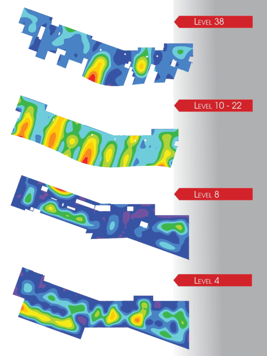 Figure 5 – BASE, Ritz Carlton Residences, Load History Deflection Plots
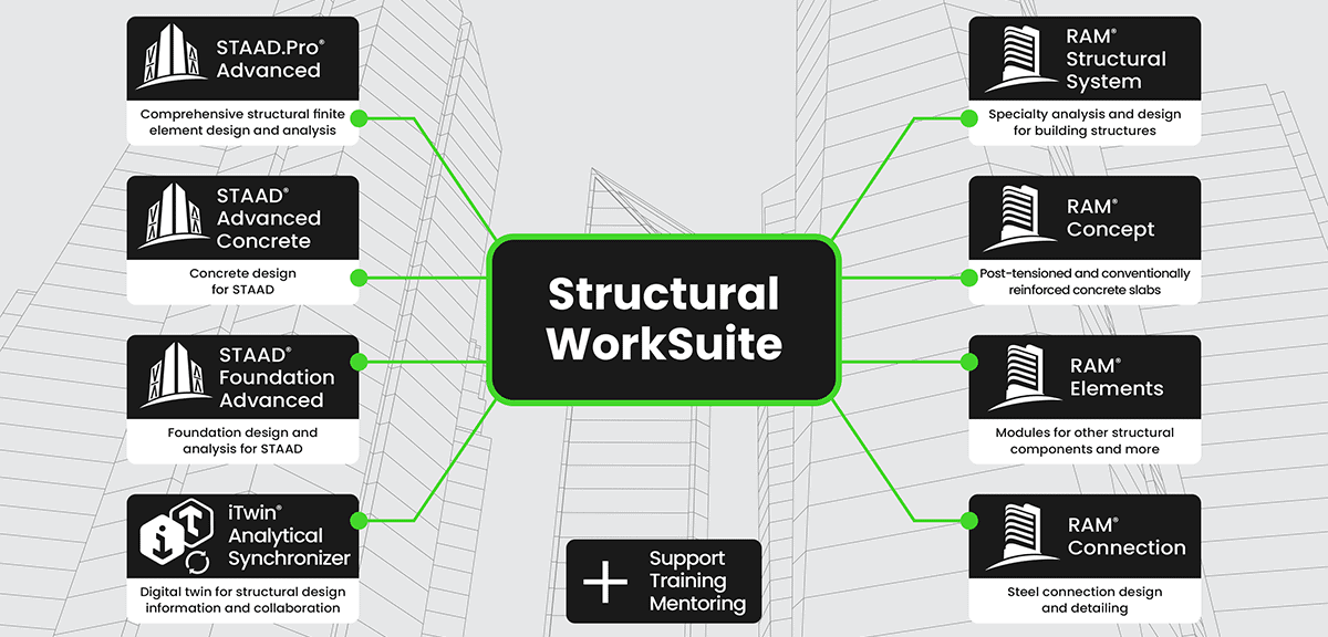
Learn more about STAAD and RAM with Virtuosity:
Attend the webinar series: Register here
Discover the Reinforced Concrete Design with STAAD and RAM series featuring blogs and webinars
For the price and the amount of Keys included in RAM Virtuoso Subscription, please visit this page.
Want to learn more about what STAAD and RAM can do for you? Don’t hesitate to contact our structural experts. We are happy to help.