This is the fifth in a series of articles on diaphragms. In the previous article I discussed the classification of Rigid diaphragms. The rigid diaphragm assumption is popular because it is easy to specify, provides a convenient method for distributing wind and seismic story forces to the frames, and analyzes quickly. In this article I will continue the discussion of Rigid diaphragms, highlighting some issues of concern that need to be understood and considered.
Axial Force Consideration
Consider a beam in a moment frame or braced frame. Because analytically the Rigid diaphragm is modeled as infinitely rigid, any two points on the diaphragm can translate and rotate, but the distance between them remains fixed. If both ends of a frame beam are attached to the Rigid diaphragm, the distance between them remains fixed; that is, there is no shortening or elongation of the beam – there is no axial strain in the beam. Since stress is a function of strain (stress = E times strain), if there is no strain there is no stress – which means no axial force. Of course this is wrong, in reality there will be axial force in the beams, but because of the Rigid diaphragm the analysis indicates zero axial force. This concept is important to understand because automated designs of these members won’t include an axial load component. This may not be significant for a moment frame beam that generally is only distributing the lateral forces to the columns; in compression the concrete floor slab may take a significant portion of that axial force, and in tension the beam may have sufficient additional capacity for the relatively small axial force. However, this can be a significant error for braced frame beams, especially for brace configurations in which the beam is a significant part of the load path in distributing the cumulative lateral force from the braces above to the braces below; these beams carry significant axial load but the analysis does not indicate that. This shortcoming of the Rigid diaphragm assumption can be rectified by selectively disconnecting some nodes from the diaphragm. For example, at each level consider disconnecting all but one of the nodes in each frame. Take care not to disconnect too many nodes, otherwise the forces will not get from the diaphragm to the frames. For chevron braces the node where the brace connects to the midspan of the beam should be disconnected from the diaphragm; the RAM Structural System automatically does this.
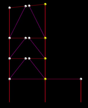
This figure shows the nodes, with the yellow nodes indicating those that are attached to the diaphragm and the white nodes indicating those that have been detached from the diaphragm. When analyzed, the forces in the diaphragms will be transferred into the frames at the yellow nodes and distributed to the adjacent nodes via axial forces in the beams, as expected:
Note that this approach will likely be conservative because it may overstate the axial load in the beams, since in reality the diaphragm forces are transferred into the frame at all of these node points, not just one and then distributed through the beams.
Obviously, nodes that are outside of the floor slab should not be connected to the Rigid diaphragm. The RAM Structural System provides tools that allow slab edges and openings to be quickly and easily modeled, and the determination of whether or not a member’s nodes are within that diaphragm – and hence attached to the Rigid diaphragm – is fully automated. With this and any other programs with similar capabilities it is important to recognize the potential that nodes intended to be (or should be) outside of the Rigid diaphragm are included in the Rigid diaphragm, and are not disconnected as they should be. Consider two different ways of modeling the slab shown in the following figure:
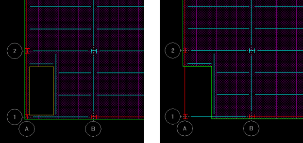
In the figure on the left, the slab edge is assigned to the perimeter framing, with an opening assigned in the interior. In the figure on the right, the slab edge cuts into the interior of the framing, leaving some framing exposed. The figure on the right is most likely the way it will actually be constructed. In the figure on the right the column at A-1 will be correctly disconnected from the diaphragm; lateral forces in the diaphragm can only be distributed to that column through axial force in the beam, not directly from the diaphragm to the column. However, in the figure on the left the column at A-1 is within the area bounded by the diaphragm edge, and so would automatically be connected to the Rigid diaphragm. In the analysis that column would be perceived to be capable of receiving lateral forces directly from the diaphragm. Remember, in a model where the diaphragm is considered to be infinitely rigid, openings in the diaphragm have no impact on the analysis results. This could have a large impact on the axial force reported by the analysis, and would certainly impact the flow of forces in the braces in braced frames. Of course, this problem could be dealt with by selectively disconnecting the node from the diaphragm, as was discussed above.
Finally, it is important to recognize that when a diaphragm has been specified as Rigid, the slab openings and even the geometry of the diaphragm itself has no influence on the analysis results. Consider this model, for example:
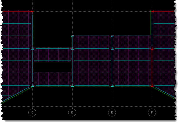
You would expect the opening and the narrow diaphragm to have a significant impact on the behavior of this structure. However, if this diaphragm has been specified as Rigid the opening and narrow width are ignored; the diaphragm doesn’t deform, the distribution of the horizontal diaphragm forces is based solely on the relative stiffnesses of the frames and their location. This could result in significant error in the distribution of lateral forces to the various frames, resulting in some frames being underdesigned and incapable of resisting the forces that they are likely to receive. This is the very reason why the building codes restrict the use of the Rigid diaphragm assumption; it is inappropriate for structures such as these.
Many diaphragms require more than simply being considered completely flexible or infinitely rigid. Often the actual stiffness of the diaphragm itself plays a key role in the distribution of the lateral forces to the various frames. The next article in this series is Classifying Semirigid Diaphragms.