
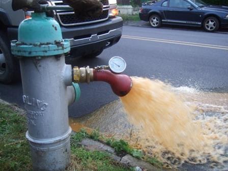
Flushing water mains is one of the accepted methods for cleaning a water main and reduce water quality complaints due to color and turbidity, or to bring fresh water with a high disinfectant residual into an area with low disinfectant residual.
 I’m occasionally asked, “What is the target minimum velocity we should be shooting for when flushing?” My answer (and my answer to many questions) is, “It depends.”
The “right” velocity depends on why you are flushing, what kind of solids that need to be moved, how they got there and what does it take to move them.
If flushing is being done to bring water with high disinfectant residual into an area with low disinfectant residual, velocity really doesn’t matter. It’s the volume of water you move that matters, and I’ll cover that use case in another blog.
Target Velocity
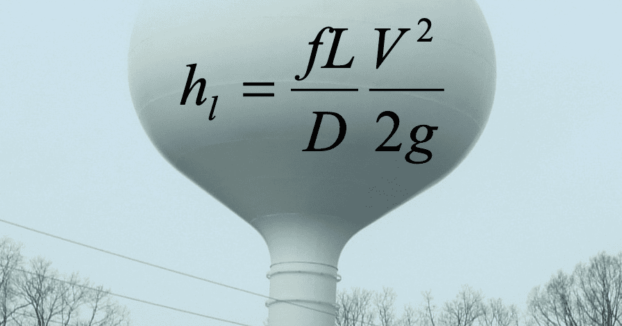
Moving solids however requires sufficient tractive stress which is usually described in terms of a scouring velocity. I’ve seen suggested velocities of 10, 8, 5, 2 ft/s (3, 2.4, 1.5, 0.6 m/s) and any number in between. I’ve not found a consensus. However, as a reality check, sewers are generally designed to achieve a minimum velocity of 2 ft/s (0.6 m/s), so if that works for sewers, it is most likely good for water mains, unless there is clear evidence (e.g. frequent red water complaints) that indicate otherwise.
Let’s just call that velocity Vtarget(or Vt). Below that velocity, there is insufficient tractive (shear) stress, and solids will settle. However, the actual velocity is not steady and can vary from less than that to greater than Vt. My thinking is that as long as you exceed Vt at some time during a day, the system will not be building up a reservoir of solids which will cause problems when velocity increases at a later time, possibly due to a fire or pipe break.
Low tractive stress (from low velocity) is usually not a problem in large transmission mains which tend to flow at a fairly high velocity. This is good because it is very difficult to dramatically increase velocity in large transmission mains with flushing. Flushing an additional 1000 gpm (63 L/s) from a hydrant through a 20 inch (510 mm) main only increases the velocity by 1 ft/s (0.3 m/s).
Mains needing cleaning are usually those in small distribution mains far from the source. These pipes are sized for fire flows with a minimum diameter of 6 inch (12 mm) in the US in most cases. The maximum velocity on normal days can be as low a 0.3 ft/s (0.1 m/s). These pipes can act as long clarifiers until some high-velocity event causes them to be problematic.
If the goal is 2 ft/s (0.6 m/s) in a 6 inch (152 mm) pipe, the flushing flow is only 175 gpm (11 L/s) in a branch pipe or 350 gpm (22 L/s) in a looped pipe (two directional flow). Such flows are easy to achieve from a single hydrant. The flow required increases proportionally with the Vt value and as a function of diameter squared.
There are essentially three areas in a distribution system;
- Pipes where the velocity is clearly above Vt and are scoured during flushing,
- Pipes far enough away that effects of flushing are not detectable,
- Pipes that have solids stirred up but not to sufficiently clean them.
The third group can cause problems after flushing is completed. One solution is to flush sufficiently long that the water and solids from all the pipes in this third group have been evacuated.
There are two general types of flushing: what I call Conventional flushing and Uni-directional flushing. With conventional flushing, the operator moves through the system in a logical pattern opening individual (or multiple hydrants). The pattern can be described by what I call Gangemi’s law: “Always flush with clean water behind you.” Start the days flushing from a source or transmission main where the water quality is good and move out from there.
However, there are cases where it is important to control the flow path to achieve a high velocity or protect customers who require very high-quality water from the temporary disruptions of flushing. This is done by closing valves to control the path that the water would take. Uni-directional flushing requires considerably more planning and operational intervention to operate the valves. There are usually issues with inoperable valves which require testing on the days before flushing or make on the spot changes in plans.
Modeling Flushing WaterGEMS
The flushing tool in WaterGEMS provides a way to plan a successful flushing program. My suggestion is to identify an area to flush on a given day, select the hydrants to flush, and run conventional flushing. If the actual velocities required are achieved, then the hydraulic part of planning is done very quickly. If there are areas for which the flow is inadequate, then use the WaterGEMS tools to plan each uni-directional flushing event. As with actual uni-directional flushing, this requires identifying the valves to close, pipe runs to clean, and hydrant(s) to flush.
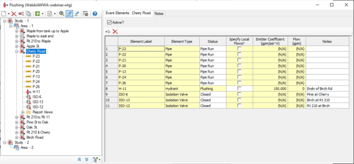
The dialog below shows how a user could set up a uni-directional flushing event by specifying the run of pipes to be scoured, the hydrant to be flushed and the valves to be opened/closed.
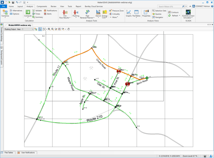
Once the flush has been specified, the operators can see a map with the elements highlighted. Orange is the flushing run, green is the flowed hydrant and red are the closed valves.
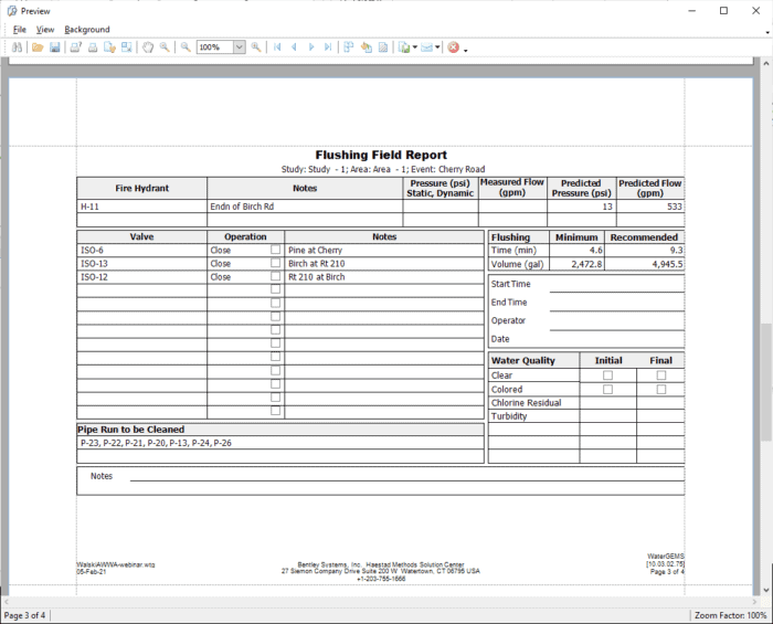
A Flushing Field report can be automatically provided to describe to field operators what needs to be done for each flush.
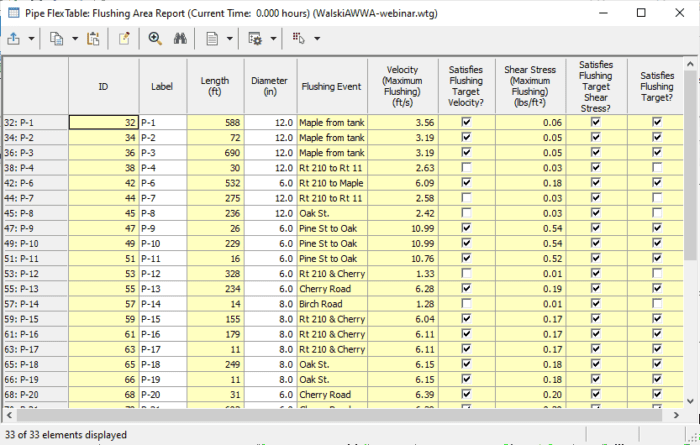
For each day’s work, a report can be developed which shows which pipes met the velocity and shear stress constants and which event was most beneficial for each pipe.
Some have claimed that flushing can remove tuberculation or scale from pipes. There is very little evidence that this is successful since these deposits are attached and aren’t readily moved. There was one exception in a water utility where I worked. They had used lime softening treatment but did not recarbonate afterward to bring down the pH. This meant that calcium carbonate precipitated out in the system. One would expect that this would form a smooth calcium scale on the pipe wall. Instead, it formed jagged roughness elements which we referred to as “sharks’ teeth”. On occasion, we would find these sharks’ teeth in the street after flushing or hydrant flow testing.
While WaterGEMS can help manage flushing programs, it remains up to the user to set the criteria for target velocity or shear stress. A good test is to isolate a section of pipe with known age and uni-directional flow during flushing. Flush at a low velocity until the water clears up; then increase the velocity until the water clears up. Continue until increasing velocity no longer brings up any additional solids. This would indicate the velocity beyond which additional velocity doesn’t provide any additional benefits.
While a hydraulic model can’t do the flushing for you, it can give a view inside the pipes to show you what’s going on underground.