Most geotechnical engineers use FEA software packages for their geotechnical design. It is especially useful for performance-based design or in situations when strong structure interaction is taking place and for which analytical solutions are not applicable.
Geotechnical engineers usually prefer to carry out 2D numerical analyses because FE models are simpler and faster to set up, plus, they are also quicker to run and post-process. On the other hand, 2D models will never fully reflect the true 3D reality of the problem at stake and might often lead to overly conservative results. However, 3D models are more accurate and realistic, but could represent a significantly larger time investment.
This article attempts to explain:
- The difference between 2D and 3D finite element analyses
- When 3D should be preferred over 2D
- Some useful modeling practices
What does 2D analysis really mean?
Even if geometries are being created in a 2D modeling environment, users should always keep in mind that the 2D FE model being created still has a 3D meaning. For a 2D plane strain configuration, the 3D significance is an “infinite” extrusion in the out-of-plane direction for which output results will be provided for a one length-unit slice (see Figure 1).
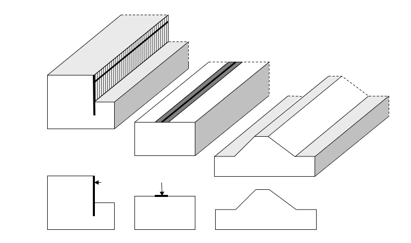
Figure 1: What does 2D plane strain mean?
For a 2D axisymmetric configuration, the 3D meaning is a 2π radian (so 360o) rotational extrusion with respect to the Y-axis direction for which output results will be provided for a one angle-unit slice (see Figure 2).
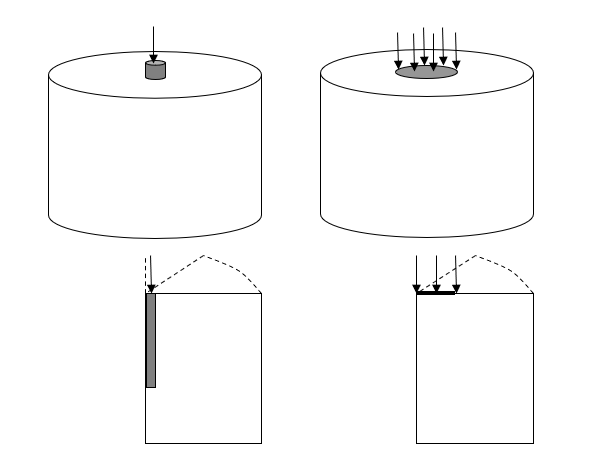
Figure 1: What does 2D plane strain mean?
What is the difference between 2D and 3D finite element analysis?
2D analyses remain attractive due to the relatively fast model set-up and calculation time. Their simplicity is clearly their biggest advantage and explains their popularity. Although 3D analyses are becoming more popular, many geotechnical engineers are reluctant to invest longer modeling time because they are judged as too costly or simply unnecessary. As a consequence, many users continue to use 2D analysis, even for situations where the real 3D geometries would not satisfy the “extrusion” requirement:
- This assumption might still be acceptable, but 3D effects would need to be accounted for empirically by the users in some ways (correction factors, averaging …) unless the 2D model is considered to be delivering conservative results.
- The user must bear in mind that 2D analyses cannot take into account the effect of stress rotation along any directions that would be contained in the 2D modeling plane (this effect is often referred to as transversal stress arching). These effects are particularly relevant in tunnel construction and for laterally loaded pile, for instance.
- Finally, it is important to realize that only an “average” soil displacement can be obtained from a 2D calculation (always the same value, whatever cross section is being considered) and that this value should remain somehow “meaningful” with respect to the true 3D nature of the problem being modeled. In this context, the detailed analysis of a singularity CANNOT be properly dealt with in the framework of a 2D calculation (for instance, a single laterally loaded pile). Only when singularities are relatively close to one another in the out-of-plane direction would a unique average soil-displacement become physically meaningful and a 2D analysis be considered as acceptable.
Why PLAXIS 3D?
PLAXIS 3D is definitely worth the time investment, especially if users already have some modeling experience with PLAXIS 2D. The modeling workflow and most of the modeling features are identical. It only takes a short time to become familiar with handling the third dimension when using construction geometry components natively.
Your 3D model does not have to be sophisticated, complex, or extensive. In that sense, it is vital to properly use symmetry, optimum geometry, and mesh definition. This aspect will be dealt with in an upcoming article.
Most accurate description of the physical reality
Most of the time, 3D models would simply need to capture the elementary stress development around structures and the associated displacement generation in the soil masses. In this context, the use of cyclic symmetry will be significantly useful in keeping the 3D model dimensions within acceptable limits. In this context, capturing the true geometrical representation of the structures and accurately modeling the soil-structure interaction is a definite advantage compared to 2D models where SSI is accounted for in a simplified manner. This, for instance, could be illustrated in the framework of the analysis of a quay wall as shown in Figure 2. Similar examples could be presented for pile row foundations and reinforced soil with rigid inclusions.
Such 2D simplified representations would necessarily require the 2D models to be calibrated or additional sensitivity analyses to be considered. This will involve a significant amount of modeling time. From that perspective, 3D models might clearly be worth the initial time investment, especially in situations where short-term and long-term analyses would require independent 2D model calibration or sensitivity checks.
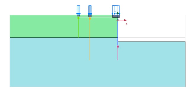
(a) 2D representation
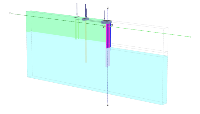
(b) 3D representation
Figure 2: Quay wall model
A powerful calibration tool
When a significantly large number of situations and assumptions must be considered in a limited study, 2D analysis will prevail. However, 3D models could be used as a powerful tool to calibrate 2D models and be considerably more accurate than analytical/simplified solutions often used in that perspective. This is particularly true for the calibration of interface stiffness required in embedded beams for the modeling of pile rows, as well as the definition of the level of soil stress deconfinement prior to the activation of the lining during tunnel construction.
Such 3D models can easily and quickly be set up (with the use of the PLAXIS 2D to 3D Converter that will presented in the next paragraph) and will certainly be more accurate than analytical solutions, especially for situations with non-isotropic initial states of stress or for the consideration of non-linear soil behavior.
The PLAXIS 2D to 3D Converter
The PLAXIS 2D to 3D Converter tool enables the creation of 3D model based on an existing 2D PLAXIS model. This considerably reduces 3D model construction time when a 2D model has already been set up. Points are extruded in lines, lines in surfaces, and surfaces in volumes. The direction of extrusion is always perpendicular to the 2D model cross section. It also maintains soil material definition and their respective assignments to soil clusters into the 3D modeling environment. Once the 2D model has been converted and the equivalent 3D model has been created, users can finalize the model with 3D-specific additions, recreate the construction stages, and run the 3D analysis.
Discover the PLAXIS Productivity Strategies series featuring blogs, LinkedIn Live sessions, and webinars.
Learn the top efficiency tips to solve your common problems.

Learn more about PLAXIS with Virtuosity:
Check out the Concept to Construction series including the PLAXIS session here.
Interested in PLAXIS soil models? Find more resources here.
Want to learn the specialized material models in PLAXIS 2D and 3D? Read here.
Get access to new educational PLAXIS videos to explore the benefits and value of using PLAXIS.
For the price and the amount of Keys included in PLAXIS Virtuoso Subscription, please visit this page.
Want to learn more about what PLAXIS can do for you? Don't hesitate to contact our geotechnical experts. We are happy to help.