In my previous post I listed and briefly described the three types of diaphragms referenced in the building codes; they include:
- Flexible
- Rigid
- Semirigid
In this article I will discuss Flexible diaphragms in greater detail.
Configurations of Flexible Diaphragms
ASCE 7-16 Section 12.3.1.1 describes configurations in which the diaphragm may be considered Flexible, generally including untopped steel decking or wood structural panels in structures where the lateral force resisting system is braced frames or shear walls. Refer to that section for other configurations as well. Note that it doesn’t say that such diaphragms must be considered Flexible, it only says that it is permitted to consider such diaphragms as Flexible. Also note that this is in the chapter on seismic design requirements; in Chapter 26 for wind loads, Section 26.2 gives a much simpler definition for “Diaphragm” that permits more configurations to be considered Rigid. For simplicity, however, I recommend that when designing for both seismic and wind loads, the same diaphragm definition and modeling be used for both, and that will generally be based on the more stringent diaphragm definition given for seismic design.
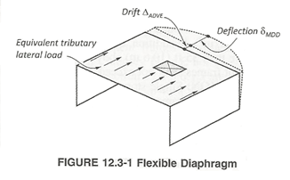
When the structural conditions do not fall within the category described in ASCE 7-16 Section 12.3.1.1, it is still permitted to consider the diaphragm as Flexible if the deflection of the diaphragm is greater than two times the drift of the adjacent frames as described in Section 12.3.1.3. A difficulty with this provision, however, is that the deflection of the diaphragm must be determined, either analytically or manually.
As can be seen, ASCE 7 has very explicit definitions of diaphragm types. In jurisdictions where other Codes are used, the requirements of those codes related to diaphragms should be investigated. Some codes merely have a general but ambiguous statement to the effect that the analysis shall consider “the influences that may reasonably be expected”, one of many of which is the diaphragms. In the Eurocodes I have only found references to diaphragms in Eurocode 8: Design of structures for earthquake resistance. Most of those references are descriptions of Rigid diaphragms, with no explicit reference to Flexible diaphragms. In lieu of explicit definitions in those codes, the definitions given in ASCE 7 are reasonable.
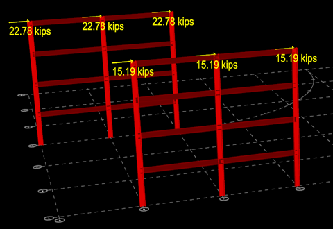
It is common that the Roof diaphragm is classified as Flexible and the floor diaphragms are classified as Rigid or Semirigid, and it is acceptable to analyze them as such. In analysis software, when considering a diaphragm as Flexible, the beams, columns, braces and walls are modeled but no element is modeled to represent the diaphragm. This simplifies the modeling of the structure but complicates the application of the loads. For Rigid and Semirigid, the diaphragm provides the analytical method for distributing the lateral forces to the frames, but since there is nothing in the model that represents the Flexible diaphragm, determination of the distribution of the lateral forces to the frames must be done manually. For seismic forces this is often based on a tributary area basis and for wind forces on a tributary exposure basis. Essentially, the loads will take the shortest path through the diaphragm to the nearest frame members.
It is crucial that the capacity of the decking and framing be investigated to verify that it is capable of transferring those forces, otherwise serious damage and even collapse may occur. If necessary, members and connections should be designed as drags to convey the lateral forces through the decking to the frames.
Because there are no diaphragm elements in the model to provide lateral bracing to the frame members, care must be taken to avoid creating conditions that are analytically unstable. This can occur, for example, if all of the columns in a frame are pinned in the weak axis; there is nothing to resist those columns from “tipping over” sideways.
An off-topic but important consideration is the ability or lack thereof of the deck to brace the top flange of the beam. If it is so flexible that it is considered a Flexible diaphragm, it may lack the stiffness required to be considered a brace of the top compression flange, in which case the beam should be designed considering the full unbraced length.
In the next article I will discuss Classifying Rigid Diaphragms.