In my previous post I discussed the definition of Flexible diaphragms, and their modeling and characteristics. In this article I will do the same for Rigid Diaphragms.
Characteristics of Rigid Diaphragms
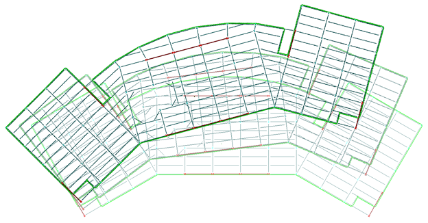
Some diaphragms, such as concrete slabs, are very stiff compared to the stiffness of the frames; the in-plane deformation of the diaphragm is negligible compared to the horizontal deflections of the frames. Such diaphragms can be classified as Rigid. Analytically, Rigid diaphragms are considered to be infinitely rigid. The Rigid diaphragm can rotate and translate, but it cannot deform. In such a model, the lateral forces will be distributed (and redistributed at subsequent levels) based upon the relative stiffnesses and location of all the members resisting lateral loads. It provides a convenient analytical tool for tying the frames together and distributing the story forces to the various frames.
ASCE 7-16 Section 12.2.1.2 gives a very narrow definition of when a diaphragm can be considered Rigid:
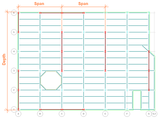
- "Diaphragms of concrete slabs or concrete-filled metal deck with span-to-depth ratios of 3 or less in structures that have no horizontal irregularities are permitted to be idealized as rigid."
Concrete slabs and composite slabs are recognized as being very stiff. The span-to-depth ratio does not refer to that of the slab itself, but rather the ratio of the distance between frames (“span”) to the width of the diaphragm (“depth”). If the diaphragm is long and narrow, it can’t be considered a Rigid diaphragm.
 Horizontal Irregularities are defined in Table 12.3-1 of ASCE 7-16. I could fill a whole article just discussing these (maybe I will).
The IBC gives a more liberal definition of Rigid diaphragm. In Section 1604.4 of IBC 2018 it states:
- "A diaphragm is rigid for the purpose of distribution of story shear and torsional moment when the lateral deformation of the diaphragm is less than or equal to two times the average story drift."
Note that this is similar but opposite of the ASCE 7 definition of Flexible. And again, it requires that the deflection of the diaphragm be determined, either analytically or manually, in order to determine whether or not the diaphragm can be modeled as Rigid.
The Eurocode allows a diaphragm to be modeled as Rigid if the corresponding Semirigid model doesn’t produce horizontal displacements that exceed the Rigid diaphragm’s model by more than 10%. The Note to Clause 4.3.1(4) of EN 1998-1:2004+A1:2013 states:
- "NOTE The diaphragm is taken as being rigid, if, when it is modelled with its actual in-plane flexibility, its horizontal displacements nowhere exceed those resulting from the rigid diaphragm assumption by more than 10% of the corresponding absolute horizontal displacements in the seismic design situation."
In some analytical programs, the Rigid diaphragm is modeled by the user defining a master node and then constraining to that node all of the other nodes at that level. In the RAM Structural System and some other programs the diaphragm is simply specified by the user as Rigid and then during the analysis process when the stiffness matrix is formed, none of the degrees of freedom associated with the diaphragm are included. This drastically reduces the size of the matrix, able to be analyzed significantly faster and with far fewer computing resources. This is one reason the assumption has been so popular since the early days of computing.
In the next article I will continue the discussion of Rigid diaphragms, focusing on some concerns and special considerations when using the assumption.
The next article in this series is Special Considerations for Rigid Diaphragms.