In my previous post I included a brief history of the consideration of diaphragms in hand calculations and analysis programs. Knowing this history helps us understand why diaphragms are considered the way they are in modern analysis programs, and even in the building codes and specifications. Most building codes identify three different diaphragm types used in analysis. The terminology that will be used here is that given in ASCE 7-16 (see Section 12.3.1):
- Flexible
- Rigid
- Semirigid
In the RAM Structural System there is an additional type that can be specified. For lack of a better term it is referred to as Pseudo-flexible. It is merely an extension of the Flexible diaphragm, with tools that automate the distribution of loads on diaphragms that are considered Flexible. This will be addressed in a future article.
Flexible Diaphragms
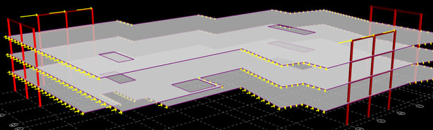
When the lateral stiffness of the frames is very large compared to the in-plane stiffness of the diaphragm, the diaphragm has very little influence on the distribution of lateral forces. Such a diaphragm is classified as Flexible. It lacks the capacity to redistribute forces between frames. In the extreme, horizontal braces are sometimes required to provide the load paths to the frames. Often with the help of drags and chords it is capable of distributing the lateral loads to the frames simply based on tributary exposure (for wind) or tributary area (for seismic). This is common for metal roof decks. These diaphragms are not represented in the analytical model in any way; the lateral model consists only of the frame members. There is no mechanism analytically to transfer the lateral forces to the frames, and so the loads must be explicitly assigned as nodal loads by the engineer. This modeling is closest to the way that analysis was done before 3D programs became available.
Rigid Diaphragms
In contrast to the Flexible diaphragm, some diaphragms are very stiff compared to the stiffness of the frames; the in-plane deformation of the diaphragm is very small compared to the horizontal deflections of the frames. Due to the lack of capacity and capabilities in early computers it became common to simplify the analytical model by assuming that the diaphragm is infinitely rigid. This is what is know as the Rigid diaphragm. The size of the computational model is reduced drastically when this assumption is made (which was necessary when computers had much less processing power). The Rigid diaphragm can rotate and translate, but it cannot deform. In such a model, the lateral forces will be distributed (and redistributed at subsequent levels) based upon the relative stiffnesses of all the members resisting lateral loads. Because concrete floors and floors of concrete fill on metal deck are generally very stiff, the Rigid diaphragm is often a suitable representation. It provides a convenient analytical tool for tying the frames together and distributing the story forces to the various frames. It is interesting to note that hand methods that were used, before computers were readily available, to attempt to distribute the loads to the frames based on the relative stiffnesses of the frames were based on an implicit assumption that the diaphragms were Rigid.
Semirigid Diaphragms
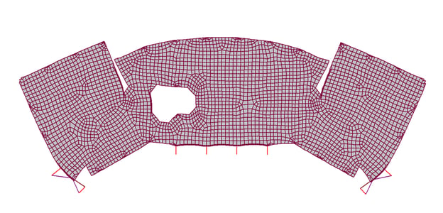
Many diaphragms don’t qualify as either Flexible or Rigid. The in-plane deformations of the diaphragm have significant influence on the distribution of lateral forces to the frames. Such diaphragms are referred to as Semirigid. To adequately capture these effects the diaphragm must be modeled and included explicitly in the analysis. This requires that the diaphragm stiffness properties be specified and the diaphragm meshed into shell or plate elements. This dramatically increases the size of the analytical model and the time that it takes to analyze. Historically this was not feasible due to the limited memory and capacity of computers, but that is no longer the case. The Rigid diaphragm assumption is still useful and can be adequately valid in many cases, but an over-reliance on the use of the Rigid diaphragm assumption has led to more and more stringent requirements in Building Codes specifying when the diaphragms must be modeled as Semirigid.
In future articles I will discuss in more detail the behavior of each of these types of diaphragms, as well issues to consider in their proper modeling.
The next article in this series is Characteristics and Modeling of Flexible Diaphragms
I would like to acknowledge the contribution of Brian Quinn and Lisa Willard from SE Solutions, LLC, to these articles. Much of this is based on a series of articles that we collaborated on that were published in Structural Engineer magazine.